Mounting expansion i/o, Minimum spacing, Panel mounting – Rockwell Automation 1769-IA8I Compact Individually Isolated 120V ac Input Module User Manual
Page 6
6
Compact™ Individually Isolated 120V ac Input Module
Publication 1769-IN012B-EN-P
IMPORTANT: A 1769-ECR or 1769-ECL right or left end cap must be used to
terminate the end of the serial communication bus.
Mounting Expansion I/O
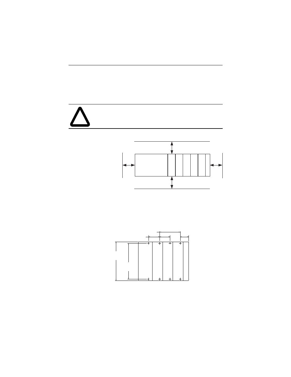
Minimum Spacing
Maintain spacing from
enclosure walls,
wireways, adjacent
equipment, etc. Allow 50
mm (2 in.) of space on all
sides for adequate
ventilation, as shown:
Panel Mounting
Mount the module to a panel using two screws per module. Use M4 or #8
panhead screws. Mounting screws are required on every module.
Panel Mounting Using the Dimensional Template
!
ATTENTION: During panel or DIN rail mounting of all
devices, be sure that all debris (metal chips, wire strands, etc.) is
kept from falling into the module. Debris that falls into the
module could cause damage on power up.
Controller
Compact I/O
Compact I/O
Compact I/O
Compact I/O
Compact I/O
End Cap
Top
Bottom
Side
Side
Host Controller
Compact I/O
Compact I/O
Compact I/O
Right End Cap
NOTE: All dimensions
are in mm (inches). Hole
spacing tolerance:
±0.4 mm (0.016 in.)
For more than 2 modules: (number of modules - 1) X 35 mm (1.38 in.)
Refer to host controller documentation for this dimension.
132
(5.197)
122.6±0.2
(4.826±0.008)
35
(1.38)
28.5
(1.12)