Derating curves – Rockwell Automation 1794-IB16D_OB16D Flex I/O 16 Input and 16 Output w/Diagnostics Module Installation Instructions User Manual
Page 5
5
Publication 1794-IN096B-EN-P - February 2004
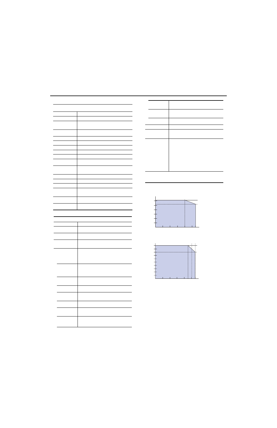
Derating Curves
1794-IB16D Input Voltage
Sensor Power
Specifications - 16 Output Module w/Diagnostics 1794-OB16D
Meets IEC 0.5A 24V dc Output Specifications
Number of Outputs
16 (1 group of 16), group isolation
Module Location
Cat. No. 1794-TB2, -TB3, -TB3S
Output Voltage
10V dc minimum
24V dc nominal
31.2V dc maximum
On-state Current
2.0mA minimum per output
0.5A per output, 8A per module maximum
Output Current Rating
8.0A (16 outputs @ 0.5A)
Surge Current
2A for 50ms, repeatable every 2s
Off-state Voltage
31.2V dc maximum
Off-state Leakage
0.5mA maximum
On-state Voltage Drop
0.5V dc at 0.5A
Isolation Voltage
Tested at 2121V dc for 1s between user and system
No isolation between individual channels
Indicators (field side
indication, customer device
driven)
16 yellow on/off status indicators (field side)
16 red diagnostic status indicators (each channel, field side)
1 red module fault indicator (field side)
Flexbus Current
60mA
Power Dissipation
4.8W maximum @ 31.2V dc
Thermal Dissipation
Maximum 16.4 BTU/hr @ 31.2V dc
Short Circuit Protect and
Detection
Thermal shutdown (auto reset)
Detection condition: when external power active, output signal
active, and output port voltage less than 2V.
Open Wire Detect off-state
leakage current
0.1mA - When external power active and output signal inactive.
Detect Reverse Polarity
Voltage
10V minimum: Module must detect if the reverse polarity external
power supply voltage is greater than the value.
General Specifications
Module Keying
Position 2
Terminal Base Screw
Torque
7 pound-inches (0.8Nm)
Dimensions (with module
installed)
1.8H x 3.7W x 2.1D inches
45.7H x 94.0W x 53.3D mm
External dc power
Supply voltage
Voltage range
24V dc nominal
10.0 to 31.2V dc (includes 5% ac ripple)
Environmental Conditions
Operating Temperature
IEC 60068-2-1 (Test Ad, Operating Cold),
IEC 60068-2-2 (Test Bd, Operating Dry Heat),
IEC 60068-2-14 (Test Nb, Operating Thermal Shock):
0 to 55°C (32 to 131°F)
Storage Temperature
IEC 60068-2-1 (Test Ab, Un-packaged Non-operating Cold),
IEC 60068-2-2 (Test Bb, Un-packaged Non-operating Dry Heat),
IEC 60068-2-14 (Test Na, Un-packaged Non-operating Thermal
Shock):
–40 to 85°C (–40 to 185°F)
Relative Humidity
IEC 60068-2-30 (Test Db, Un-packaged Non-operating
Damp Heat):
5 to 95% non-condensing
Vibration
IEC60068-2-6 (Test Fc, Operating):
5g @ 10-500Hz
Shock
IEC60068-2-27 (Test Ea, Unpackaged shock)
Operating 30g
Non-operating 50g
Emissions
CISPR 11:
Group 1, Class A (with appropriate enclosure)
ESD Immunity
IEC 61000-4-2:
6kV contact discharges
8kV air discharges
Radiated RF Immunity
IEC 61000-4-3:
10V/m with 1kHz sine-wave 80%AM from 80MHz to 2000MHz
10V/m with 200Hz 50% Pulse 100%AM at 900Mhz
10V/m with 200Hz 50% Pulse 100%AM at 1890Mhz
EFT/B Immunity
IEC 61000-4-4:
±2kV at 5kHz on signal ports
±2kV at 5kHz on power ports
Surge Transient
Immunity
IEC 61000-4-5:
±1kV line-line(DM) and ±2kV line-earth(CM) on signal ports
±1kV line-line(DM) and ±2kV line-earth(CM) on power ports
Conducted RF Immunity
IEC 61000-4-6:
10Vrms with 1kHz sine-wave 80%AM from 150kHz to 80MHz
Enclosure Type Rating
None (open-style)
Conductors
Wire Size
Category
1
12AWG (4mm
2
) stranded copper wire rated at 75°C or higher
3/64 inch (1.2mm) insulation maximum
2
Certifications (when
product is marked)
2
C
UL
US
UL Listed Industrial Control Equipment, certified for US and
Canada
C
UL
US
UL Listed for Class I, Division 2, Groups A, B, C and D
Hazardous locations certified for US and Canada
CSA CSA certified for Class I, Division 2, Groups A, B, C and D
Hazardous locations
CE
2
European Union 89/336/EEC EMC Directive,
compliant with:
EN 61000-6-4; Industrial Emissions
EN 50082-2; Industrial Immunity
EN 61326; Meas./Control/Lab., Industrial Requirements
EN 61000-6-2; Industrial Immunity
C-Tick
2
- Australian Radiocommunications Act compliant with
AS/NZS CISPR 11, Industrial Emissions
1
You use this category information for planning conductor routing as described in Allen-Bradley
publication 1770-4.1, Industrial Automation Wiring and Grounding Guidelines.
2
For the latest up-to-date information, see the Product Certification link at www.ab.com for Declarations of
Conformity, Certificates and other certification details. For notification of any additional release notes, refer to
www.ab.com/manuals/.
0
5
10
15
25
20
30
10 20 30 40 50
55
31 .2
26 .4
Ambient Temperature (˚C)
Input
Voltage
(V)
10 20 30 40 50
55
0
10
20
30
40
50
45
Sensor
Power
(m A )
Current
Ambient Temperature (˚C)