Connect wiring for the 1794-tbn – Rockwell Automation 1794-IF4I FLEX I/O 4 Isolated Input Module User Manual
Page 3
FLEX™ I/O Isolated Input Analog Module 3
Publication 1794-IN038E-EN-P - November 2011
5. If continuing DC common to the next base unit, connect a jumper from
terminal 33 (common) on this base unit to terminal 16 on the next base
unit.
6. 1794-TB3T, 1794-TB3TS only: Connect cable shield to terminals 39…46
on row (C).
7. 1794-TB2, 1794-TB3, 1794-TB3S: Connect wiring shields to functional
earth ground as near as possible to the module.
1794-TB2, 1794-TB3, 1794-TB3S, 1794-TB3T and 1794-TB3TS Terminal Base
Wiring
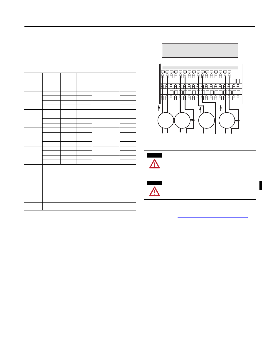
Connect Wiring for the 1794-TBN
1. Connect individual input wiring to numbered terminals on row (B) as
Wiring Connections for the 1794-IF4I Input Module
table.
2. Connect the associated input common/return to the corresponding
terminal on row (C) for each input as indicated in the table.
3. Connect +V DC power to terminal 34 on row (C).
4. Connect DC common/return to terminal 16 on row (B).
5. If continuing power to the next terminal base, connect a jumper from
terminal 51 (+V DC) on this base unit to terminal 34 on the next base unit.
6. If continuing DC common to the next base unit, connect a jumper from
terminal 33 (common) on this base unit to terminal 16 on the next base
unit.
7. Connect wiring shields to functional earth ground as near as possible to
the module.
Wiring Connections for the 1794-IF4I Input Module
Channel
Signal Type
Label
Markings
1794-TB2, 1794-TB3, 1794-TB3S,
1794-TB3T, 1794-TB3TS
1794-TBN
Terminal
Shield (1794-TB3T,
1794-TB3TS)
Terminal
0
Current
I0
A-0
C-39
B-0
Current
I0 ret
A-1
C-1
Voltage
V0
A-2
C-40
B-2
Voltage
V0 ret
A-3
C-3
1
Current
I1
A-4
C-41
B-4
Current
I1 ret
A-5
C-5
Voltage
V1
A-6
C-42
B-6
Voltage
V1 ret
A-7
C-7
2
Current
I2
A-8
C-43
B-8
Current
I2 ret
A-9
C-9
Voltage
V2
A-10
C-44
B-10
Voltage
V2 ret
A-11
C-11
3
Current
I3
A-12
C-45
B-12
Current
I3 ret
A-13
C-13
Voltage
V3
A-14
C-46
B-14
Voltage
V3 ret
A-15
C-15
-V DC common
1794-TB2, 1794-TB3, 1794-TB3S: Terminals B-16…B-33 are internally connected in the
terminal base unit.
1794-TBN: Terminals B-16 and B-33 are internally connected in the terminal base unit.
1794-TB3T, 1794-TB3TS: Terminals 16, 17, 19, 21, 23, 25, 27, 29, 31 and 33 are internally
connected in the terminal base unit.
+V DC power
1794-TB3, 1794-TB3S: Terminals C-34…C-51 are internally connected in the terminal base
unit.
1794-TB3T, 1794-TB3TS: Terminals C-34, C-35, C-50 and C-51 are internally connected in the
terminal base unit.
1794-TB2, 1794-TBN: Terminals C-34 and C-51 are internally connected in the terminal base
unit.
Chassis ground
(shield)
1794-TB3T, 1794-TB3TS: Terminals C-39…C-46 are internally connected to chassis ground.
ATTENTION
Connect only one current or one voltage signal per channel. Do not
connect both current and voltage on one channel.
ATTENTION
Do not remove or replace a Terminal Base unit while power is applied.
Interruption of the backplane can result in unintentional operation or
machine motion.
I
+
+
-
+
+
-
I
+
I
+
-
0 1 2 3 4 5 6 7 8 9 10 11 12 13 14 15
16 17 18 19 20 21 22 23 24 25 26 27 28 29 30 31 32 33
34 35 36 37 38 39 40 41 42 43 44 45 46 47 48 49 50 51
45751
Row A
Row B
Row C
Current
input
Current
input
Current
input
Voltage
input
AC or DC
4-wire current
transmitter
DC only
3-wire current
transmitter
Current only
2-wire current
transmitter
DC only
3-wire
transmitter
Label placed at top of wiring area
Row A
Row B
Row C
1794-TB3S shown