Connection of voltage supply to input device – Rockwell Automation 1753-IB16 GuardPLC Digital Input Module Installation Instructions User Manual
Page 7
GuardPLC Digital Input Module 7
Rockwell Automation Publication 1753-IN004C-EN-P - June 2010
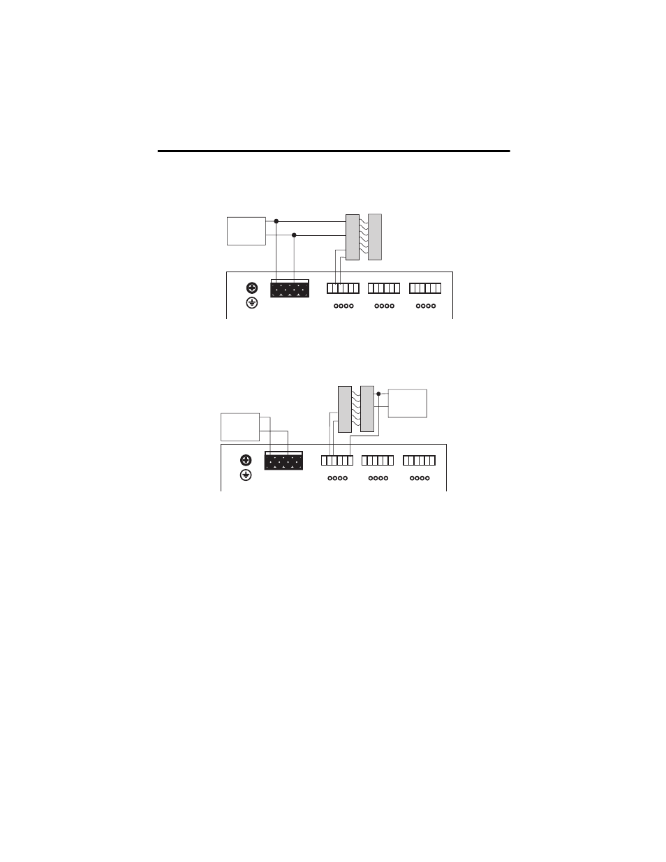
If devices require 24V DC to operate and use the same power source as the module, then wire the
outputs of the device directly to inputs on the module.
Devices with their own dedicated power supply can also be connected. Connect the reference
pole of the external power supply to the L- reference pole of the input.
The safe state of an input is indicated by a 0 signal being passed to the user program. If the test
routines detect a fault in the digital inputs, a 0 signal is processed in the user program for the
defective channel. When a fault occurs, the inputs are switched off (0) and the FAULT indicator
is activated.
Follow the closed-circuit principle for external wiring when connecting sensors. To create a safe
state in the event of a fault, the input signals revert to the de-energized state (0). Although the
external line is not monitored, a wire break is interpreted as a safe (0) signal.
COM
24V DC
Power
Supply
COM
+
+
Light Curtain
(or any Safety Input)
L-
L-
L+
L+
24V DC
1
LS+
LS+
LS+
L-
D1
2 3 4
1
2
3 4
5
6
5
L-
D1
6 7 8
9
L-
D1
10 11 12
1
2
3 4
5
6
7 8
9 10 11 12
7 8
9 10 11 12
13 14 15 16 17 18
13 14 15 16 17 18
Connection of Voltage Supply to Input Device
24V DC
Power
Supply
COM
COM
+
24V DC
Power
Supply
COM
+
+
Light Curtain
(or any Safety Input)
L-
L-
L+
L+
24V DC
1
LS+
LS+
LS+
L-
D1
2 3 4
1
2
3 4
5
6
5
L-
D1
6 7 8
9
L-
D1
10 11 12
1
2
3 4
5
6
7 8
9 10 11 12
7 8
9 10 11 12
13 14 15 16 17 18
13 14 15 16 17 18
Connection of Devices with Dedicated Power Supplies