Module ch1 ch2 ch3 – Rockwell Automation 1769-SM2 Compact I/O DSI/Modbus Network Communication Module User Manual
Page 4
4
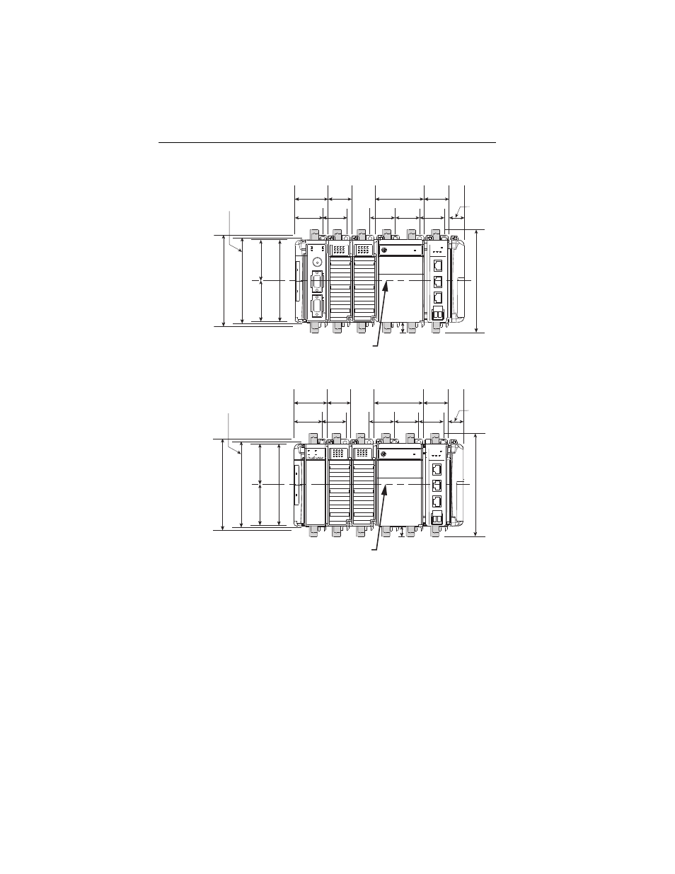
Figure 2 1769-SM2 Module with CompactLogix Controller
Figure 3 1769-SM2 Module with Remote 1769-Based Adapter
Using Module as a Template
The following procedure enables you to use the assembled modules as a
template for drilling holes in the panel. Due to module mounting hole
tolerance, it is important to follow these steps:
a. On a clean work surface, assemble no more than three modules.
b. Using the assembled modules as a template, carefully mark the
center of all module-mounting holes on the panel.
c. Return the assembled modules to the clean work surface, including
any previously mounted modules.
d. Drill and tap the mounting holes for the recommended M4 or #8
screw.
132 mm (5.19 in)
122.6 mm (4.83 in)
118 mm (4.65 in)
147.4 mm (5.81 in)
14.7 mm
(0.58 in)
35 mm
(1.38 in)
35 mm
(1.38 in)
28.5 mm
(1.12 in)
35 mm
(1.38 in)
70 mm
(2.76 in)
35 mm
(1.38 in)
35 mm
(1.38 in)
35 mm
(1.38 in)
50 mm
(1.97 in)
40 mm
(1.58 in)
59 mm
(2.32 in)
59 mm
(2.32 in)
Mounting Hole
Dimension
DIN Rail
Center Line
DSI
MODULE
CH1
CH2
CH3
C
H
1
C
H
2
C
H
3
DSI
MODULE
CH1
CH2
CH3
C
H
1
C
H
2
C
H
3
132 mm (5.19 in)
122.6 mm (4.83 in)
118 mm (4.65 in)
147.4 mm (5.81 in)
14.7 mm
(0.58 in)
35 mm
(1.38 in)
35 mm
(1.38 in)
28.5 mm
(1.12 in)
35 mm
(1.38 in)
70 mm
(2.76 in)
35 mm
(1.38 in)
35 mm
(1.38 in)
35 mm
(1.38 in)
50 mm
(1.97 in)
40 mm
(1.58 in)
59 mm
(2.32 in)
59 mm
(2.32 in)
Mounting Hole
Dimension
DIN Rail
Center Line
MS
IO
NS
DIAG