Module configuration, Dip switches, Dip switch 1 settings – Rockwell Automation 1747-DCM Direct Communication Module User Manual
Page 7
Direct Communication Module 7
Publication 1747-IN005B-EN-P - March 2003
Module Configuration
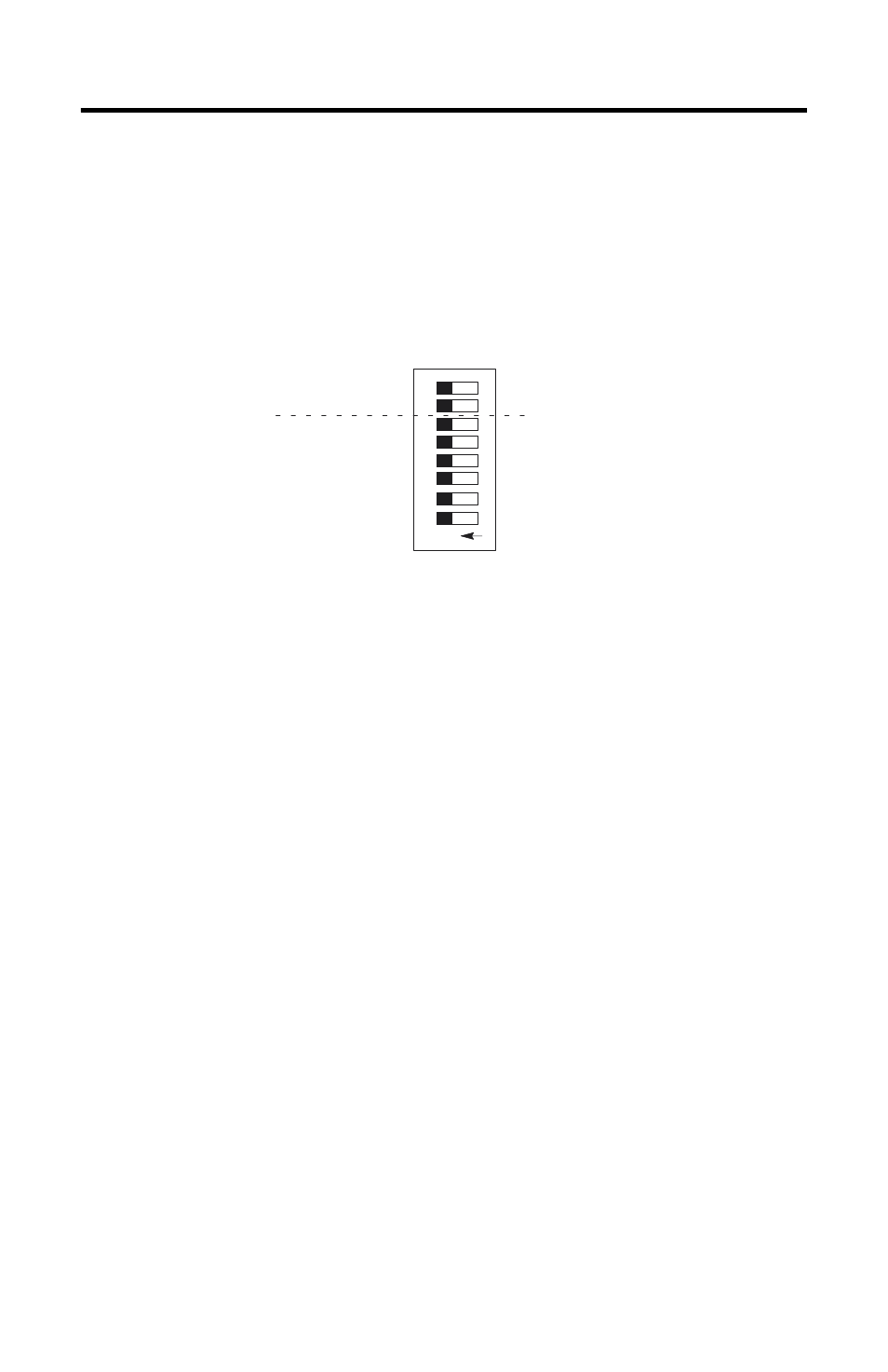
DIP Switches
DIP switches enable the 1747-DCM to properly interpret the RIO system addressing.
The 1747-DCM has two banks of DIP switches mounted on its circuit board. Each
bank contains eight switches. The default settings are shown below.
DIP Switch 1 Settings
Chassis Address (SW1-1 through SW1-6)
The chassis address refers to the logical chassis number from the scanner image
that contains a particular 1747-DCM’s image.
The table on the following page shows the settings that define possible chassis
address choices for all scanners. To use this table, first determine which of the
following categories applies to your scanner.
•
PLC-2, mini-PLCs, PLC-2/30 with 1770-SD, SD2 remote scanner
•
PLC-3 and PLC-5/250 processors (This category includes those with built-in
scanners, as well as the following, without built-in scanners: 1775-54A, -54B,
-S5, SR, -SR5, and 5250-RS.)
•
SLC-5/02 (or above) with 1747-SN scanner
After determining which category applies to your 1747-DCM application:
1. Find the column for the scanner used in your application.
2. Go down the column to the chassis address that you assigned to the
1747-DCM.
3. Use the switch settings in the right-most columns of the table that
correspond to your chassis address.
8
O
N
12
3
4
5
6
7
Starting I/O Group Number
Chassis Address