Key the backplane connector, Install the module and field wiring arm – Rockwell Automation 1771-OW16/B Electro Mechanical Relay Contact Output Module User Manual
Page 7
Publication 1771-IN069B-EN-P - November 2005
Electromechanical Relay Contact Output Module 7
Key the Backplane
Connector
Place your module in any slot in the chassis except the leftmost slot which is
reserved for processors or adapters.
Install the Module and Field
Wiring Arm
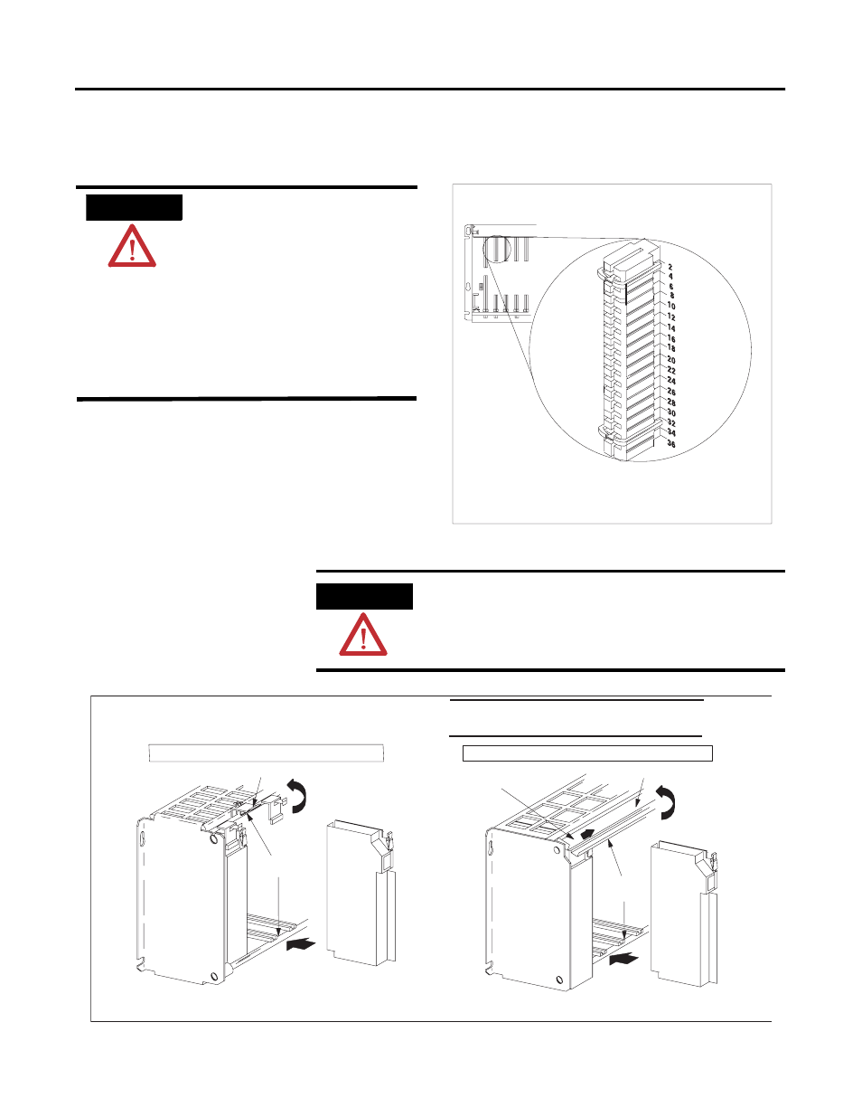
11022-I
Position keying bands in the backplane connectors to
correspond to the key slots on the module.
Place the keying bands:
- between 2 and 4
- between 32 and 34
You can change the position of these bands if subsequent system
design and rewiring makes insertion of a different type of module
necessary.
Upper Connector
I/O Chassis
Observe the following precautions
when inserting or removing keys:
• insert or remove keys with
your fingers
• make sure that key placement
is correct
Incorrect keying or the use of a tool
can result in damage to the backplane
connector and possible system faults.
ATTENTION
WARNING
If you connect or disconnect wiring while field-side power
is on, an electrical arc can occur. This could cause an
explosion in hazardous locations. Be sure that power is
removed or the area is nonhazardous before proceeding.
1771-A1B, -A2B, -A3B, -A3B1, -A4B I/O Chassis
1771-A1B, -A2B, -A3B1, -A4B Series B I/O Chassis
Snap the chassis latch over
the top of the module to secure it.
locking tab
Module
Module
card guides
card guides
locking bar pin
locking bar
Swing the chassis locking bar down into place to secure
the module. Make sure the locking pins engage.
Place the module in the card guides at the top and bottom
of the I/O chassis that guide the module into position.
Important
Apply firm even pressure on the module to seat
it in its backplane connector.