Rockwell Automation 1770-SC A-B Data Highway/Data Highway+ Installation Date User Manual
Page 2
D
Da
atta
a H
Hiig
gh
hw
wa
ay
y//D
Da
atta
a H
Hiig
gh
hw
wa
ay
y P
Pllu
uss
S
Stta
attiio
on
n C
Co
on
nn
ne
ec
ctto
orr
D
Drro
op
plliin
ne
e P
Prre
ep
pa
arra
attiio
on
n
(continued)
3
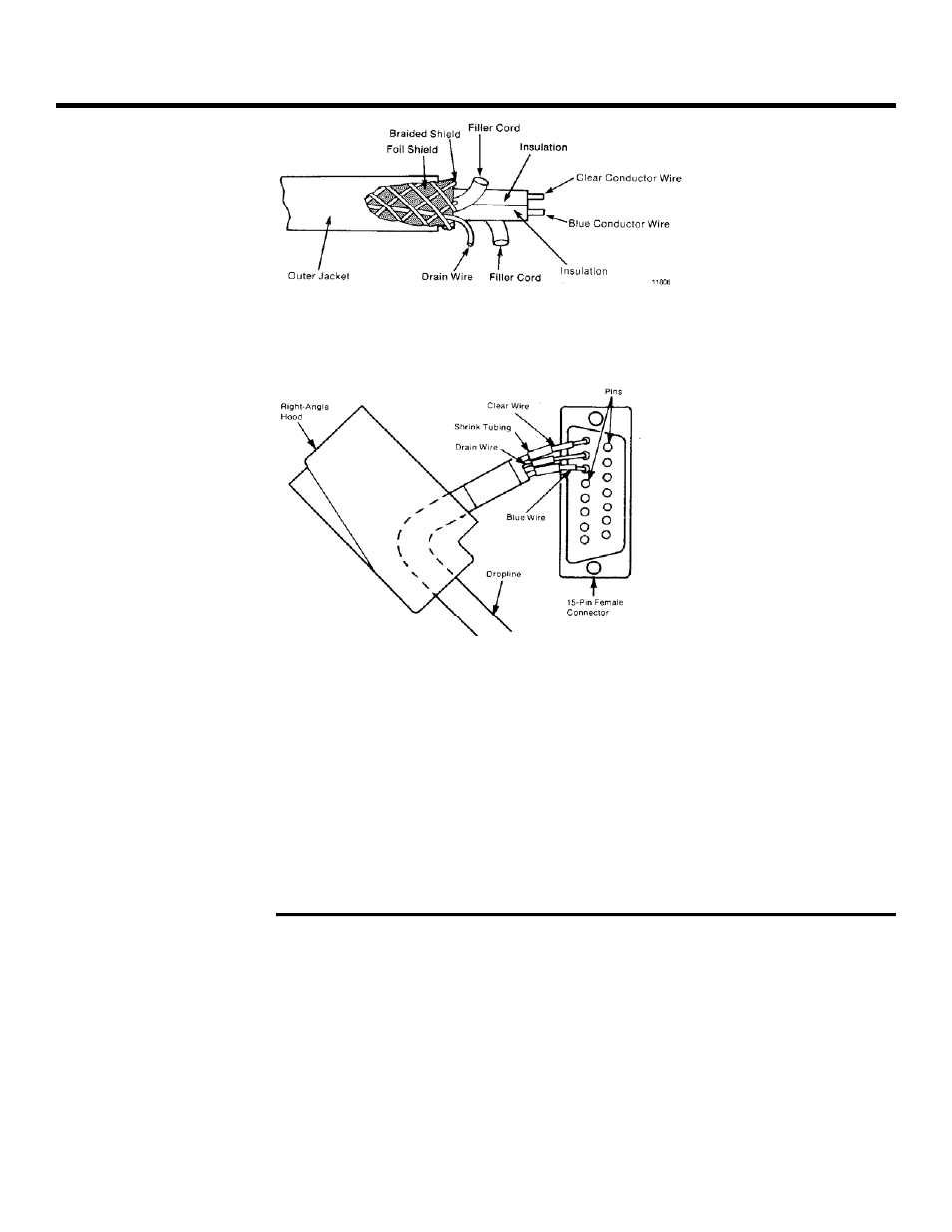
3.. Insert the prepared cable end through the circular hole in the hood of the D-shell
connector. Insert about 1/2 inch of shrink tubing over the ends of the three
conductors.
4
4.. Solder the blue, clear, and drain wires into their corresponding connector pins in
the back of the 15 pin female connector. Connect the blue wire to pin 6, drain wire
to pin 7, and clear wire to pin 8.
5
5.. Slide the shrink tubing forward over the soldered connections and shrink the
tubing with a heat gun.
6
6.. Assemble the 15-pin connector to the D-shell hood.
7
7.. At the other end of the dropline cable, carefully remove about three inches of
insulation, foil, braided shield, and filler cord, freeing the drain wire, clear and blue
insulated wires. Strip about 1/4 inch of insulation from the ends of the insulated
wires.
1
1.. Remove the cover and the terminal blocks from the enclosure and mount the
enclosure at the point where you want to add the dropline.
IIm
mp
po
orrtta
an
ntt:: Removing the terminal block allows you to make connections to the
screw-clamp terminals more easily.
2
2.. Cut the trunkline cable. Feed the incoming and outgoing trunkline cable through
their respective cable clamps at the top of the enclosure.
3
3.. Carefully remove about three inches of cable insulation, foil, braided shield, and
filler cord, freeing the drain wire, clear and blue insulated wires. Strip about 1/4
inch of insulation from the ends of the insulated wires.
T
Trru
un
nk
klliin
ne
e P
Prre
ep
pa
arra
attiio
on
n