Field wiring connections, Grounding the module, Output wiring – Rockwell Automation 1769-OW8I Compact Individually Isolated AC/DC Relay Output Module User Manual
Page 8
8 Compact™ Individually Isolated AC/DC Relay Output Module
Publication 1769-IN053A-EN-P - April 2001
Field Wiring Connections
Grounding the Module
This product is intended to be mounted to a well-grounded mounting surface such
as a metal panel. Additional grounding connections from the module’s mounting
tabs or DIN rail (if used), are not required unless the mounting surface cannot be
grounded. Refer to Industrial Automation Wiring and Grounding Guidelines,
Allen-Bradley publication 1770-4.1, for additional information.
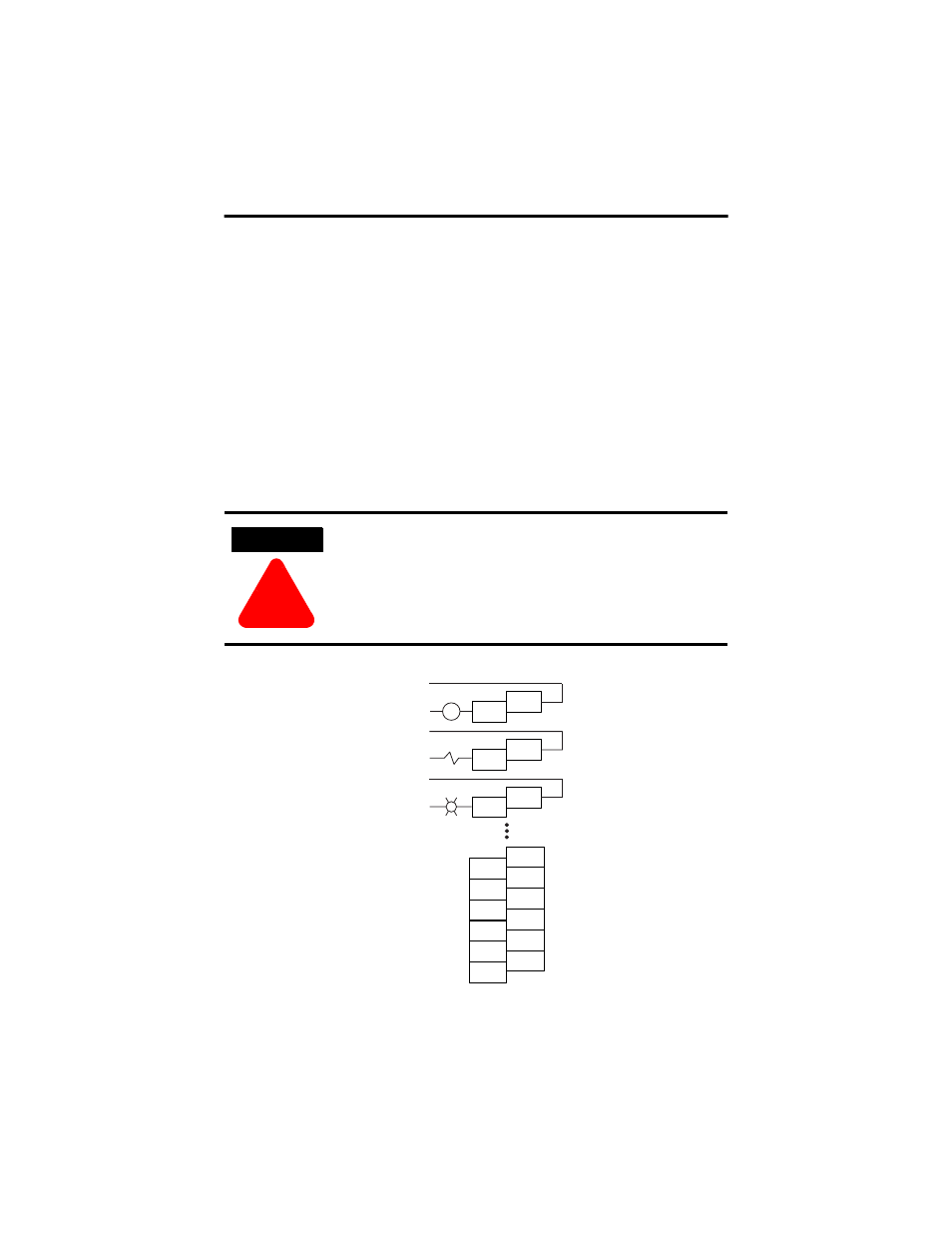
Output Wiring
Basic wiring
(1)
of output devices to the 1769-OW8I is shown below.
ATTENTION
!
Be careful when stripping wires. Wire fragments that fall into a
module could cause damage at power up. Once wiring is
complete, ensure the module is free of all metal fragments.
(1)
Surge Suppression - Connecting surge suppressors across your external inductive load will extend the life of the relay
contacts. For additional details, refer to Industrial Automation Wiring and Grounding Guidelines, Allen-Bradley publication
1770-4.1.
L1a or +DCa
L2a or -DCa
OUT 0
OUT 6
OUT 5
OUT 4
OUT 3
OUT 7
VAC-VDC
5
VAC-VDC
4
VAC-VDC
3
VAC-VDC
6
NC
VAC-VDC
7
NC
VAC-VDC
0
CR
L1b or +DCb
L2b or -DCb
OUT 1
VAC-VDC
1
L1c or +DCc
L2c or -DCc
OUT 2
VAC-VDC
2