Key the backplane connector, Setting the delay time jumper – Rockwell Automation 1771-IAD AC/DC (120V)Input Installation Instructions User Manual
Page 5
AC/DC (120V) Input Module
5
Publication 1771ĆIN023B-EN-P - August 2002
Your module is equipped with an adjustable delay time jumper. Use
the jumper to select between two input channel delay times. The
delay time you choose applies to all sixteen of the module’s
channels.
Use this delay time:
If you want:
5ms
to detect typical input readings
20ms
to prevent detection of false inputs in highĆnoise environments
The module is shipped with the delay time jumper preset to 5ms. To
change the delay time jumper to 20ms, do the following:
1. Locate the delay time jumper selection plug at the top-right edge
of the module circuit board, as shown in the following figure.
20ms
5ms
TopĆright edge of circuit board
Delay Time Jumper
(shown in preset 5ms
position)
2. Use your finger to slide the jumper off the 5ms position (the
middle post and the right post).
3. Carefully reposition the jumper by sliding it onto the 20ms
position (the middle post and the left post).
Key the Backplane
Connector
Place your module in any slot in the chassis
except the leftmost slot which is reserved for
processors or adapters.
Observe the following precautions
when inserting or removing keys:
•
insert or remove keys with
your fingers
•
make sure that key placement
is correct
Incorrect keying or the use of a tool
can result in damage to the
backplane connector and possible
system faults.
!
ATTENTION
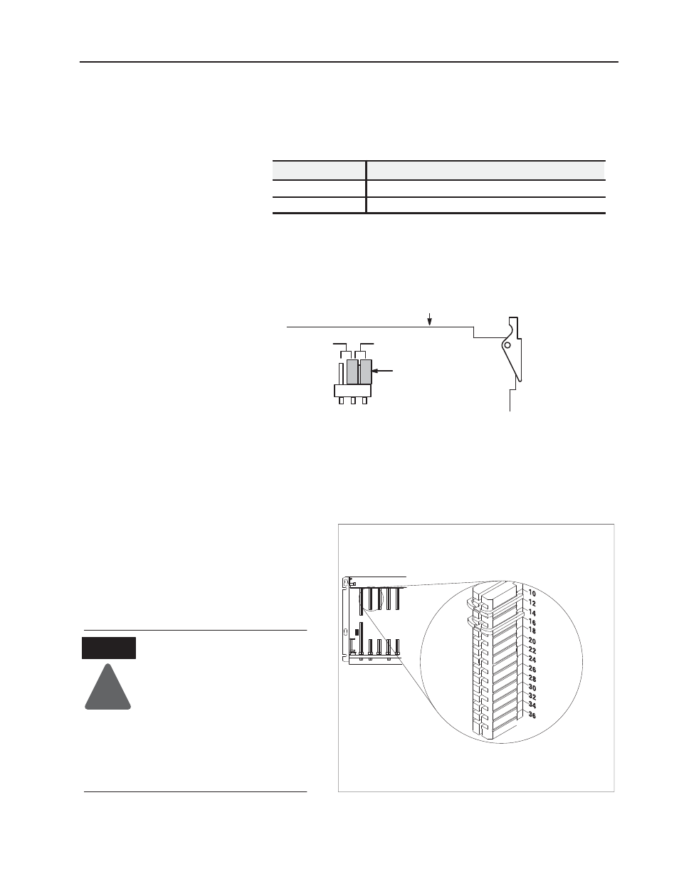
Position the keying bands in the backplane connectors to correspond to
the key slots on the module.
Place the keying bands:
- between 10 and 12
- between 14 and 16
You can change the position of these bands if
subsequent system design and rewiring makes
insertion of a different type of module necessary.
Upper
Connector
11022ĆI
I/O chassis
Setting the Delay Time
Jumper