Specifications – Rockwell Automation 1794-OB8EPXT, 1794-IB16XT, 1794-OB16PXT, 1794-IB10XOB6XT FLEX XT I/O Digital DC Input/Output Modules User Manual
Page 5
5
Publication 1794-IN124A-EN-P - January 2009
Programming the 1794-OB8EPXT
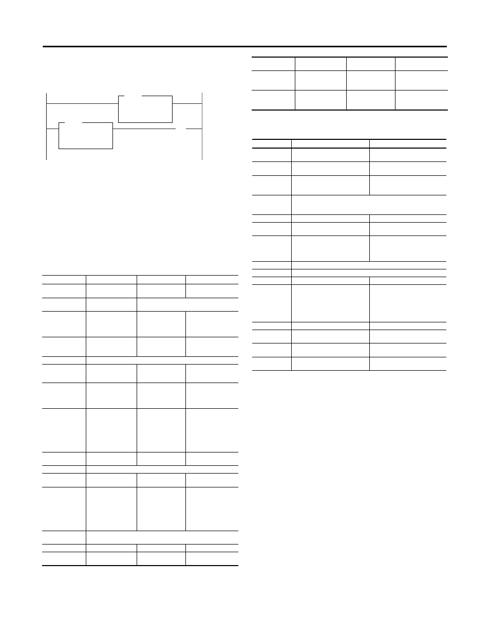
If your program automatically checks for fault bits, bits 8…15 of read word
1 must be masked. This is a sample program for a module at rack address
1, group 0. Add similiar rungs to your program.
Resetting a Fault on the 1794-OB8EPXT
Faults can be reset 3 ways: press the fault reset button on the front of the
module; or toggle the output reset bit (write word 1, bit 08); or cycle
backplane power.
Using the Reset Button on the 1794-OB8EPXT
When you press the reset button, the fault indicator for the faulted output
turns off for about 1.2 s. After the delay, the faulted output attempts to turn
on. If the external condition causing the fault is corrected, the output will
remain on, the fault indicator is off, and the status indicator is on.
Specifications
Output Modules
Input Modules
Attribute
1794-OB8EPXT
1794-OB16PXT
1794-IB10XOB6XT
Number of outputs
8 (1 group of 8),
nonisolated, sourcing
16 nonisolated,
sourcing
6 nonisolated, sourcing
Module location
Cat. No. 1794-TB2, -TB3,
-TB3S, -TBN
Cat. No. 1794-TB2, -TB3, -TB3S
On-state current
1.0 mA min. per channel
2.0 A max. per channel
1.0 mA min. per
channel
500 mA max. per
channel
2.0 mA min.
8.0 mA nom. at 24V DC
11.0 mA max.
On-state voltage
range
19.2 V DC min)
24 V DC nom.
31.2 V DC max.
10 V DC min.
24 V DC nom.
31.2 V DC max.
10 V DC min.
24 V DC nom.
31.2 V DC max.
Supply voltage
24V DC nom.
Voltage range
19.2V DC to 31.2V DC
10V DC to 31.2V DC
10 to 31.2 V DC (includes
5% AC ripple)
Supply current
55mA @ 24V DC
35 mA @ 24V DC
15 mA @ 19.2 V DC
19 mA @ 24 V DC
8 mA @ 10V DC
25 mA @ 31.2V DC
Output current
rating
Max. 2.0 A per output,
10.0 A max. per module
(for example, 8 outputs
@ 1.25 A, 5 outputs @
2.0 A, or similar
combinations totaling
10.0 A or less)
8.0 A (16 outputs @
0.5A)
2.0 A per output
10.0 A max. per module
Surge current
4.0 A for 10 ms,
repeatable every 3 s
1.5 A for 50 ms,
repeatable every 2 s
4.0 A for 50 ms,
repeatable every 2 s
Off-state leakage
0.5 mA max.
On-state voltage
drop
0.2 V DC max.
0.5 V DC max.
1.0 V DC @2 A,
0.5 V DC@1 A max.
Isolation voltage
50V (continuous), Basic
Insulation Type
No isolation between
individual channels
Type tested at 1500V AC
for 60 s, between field
side and system
50V (continuous), Basic
Insulation Type
No isolation between
individual channels
Type tested at 2550V
DC for 60 s, between
field side and system
50V (continuous), Basic
Insulation Type
No isolation between
individual channels
Type tested at 1365V AC
for 60 s, between field
side and system
Output signal delay
Off to On - 0.5 ms max.
On to Off - 1.0 ms max.
Flexbus current
80 mA
60 mA
35 mA
Power dissipation
5 W maximum @ 31.2 V
DC
5.0 W maximum @
31.2 V DC
6.0 W maximum @ 31.2
V DC
MVM
CMP
Source
Mask
Destination
MASKED MOVE
Compare
Expression
N9: < > 0
I:010
FF00
N9:0
O:000
( Out )
This rung turns on output if a fault occurs.
This rung masked bits 8 thru 15.
Thermal dissipation
Max. 17.1 BTU/hr @
31.2 V DC
Max. 17.0 BTU/hr @
31.2 V DC
Max. 20.3 BTU/hr @
31.2 V DC
Indicators (field side
indication, logic
driven)
8 yellow status
indicators
8 red fault indicators
16 yellow status
indicators
6 yellow status
indicators
Fusing
Outputs are
electronically fused
Outputs are
electronically
protected
Module outputs are not
fused.
(1)
(1)
Fusing is recommended. If fusing is desired, you must supply external fusing. Use SAN-O MQ4-3A or Litteolfuse
235-003 fuses.
Attribute
1794-IB10XOB6XT
1794-IB16XT
Number of inputs
10, nonisolated, sinking
16 (1 group of 16), nonisolated,
sinking
Module location
Cat. No. 1794-TB2, -TB3, -TB3S
Cat. No. 1794-TB3, -TB3S Terminal
Base Unit
On-state current
2.0 mA min.
8.0 mA nom. at 24V DC
11.0 mA max.
2.0 mA min.
3.0 mA nom. at 24V DC
5.0 mA max.
On-state voltage
range
10 V DC min.
24 V DC nom.
31.2 V DC max.
Supply voltage
24V DC nom.
24V DC nom,
Voltage range
10 to 31.2 V DC (includes 5% AC
ripple)
10V DC to 31.2V DC
Supply current
15 mA @ 19.2 V DC
19 mA @ 24 V DC
8 mA @ 10V DC
25 mA @ 31.2V DC
4 mA @ 24V DC
Off-state voltage
5.0 V DC max.
Off-state current
1.5 mA min.
Input impedance
4.8 K
Ω
Isolation voltage
50V (continuous), Basic Insulation
Type
No isolation between individual
channels
Type tested at 1365V AC for 60 s,
between field side and system
50V (continuous), Basic Insulation
Type
No isolation between individual
channels
Type tested at 850V AC for 60 s,
between field side and system
Flexbus current
35 mA
30 mA
Power
dissipation
6.0 W maximum @ 31.2 V DC
2 W max. @ 31.2V DC
Thermal
dissipation
Max. 20.3 BTU/hr @ 31.2 V DC
Max 9.2 BTU/hr @ 31.2V DC
Indicators
10 yellow status indicators
(Logix side indication, Logic driven)
16 yellow status indicators
(field side indication, logic driven)