Key the backplane connector, Calculate power supply requirements – Rockwell Automation 1771-IVN Installation Data dc (10-30V) Input Module User Manual
Page 5
DC (10–30V) Input Module
5
Publication 1771-IN035B-EN-P - July 2002
This module has input filtering to limit the effect of voltage
transients caused by contact bounce and/or electrical noise.
Specifications for input filtering are listed in the specifications at the
end of this document.
Your module receives its power for internal logic circuitry through
the 1771 I/O chassis backplane from the chassis power supply. The
module requires 280mA from the output of this supply. To calculate
the requirements for the backplane power supply, add 280mA to the
power requirements of all other modules in the I/O chassis.
Calculating the requirements will prevent an overload to the chassis
backplane and/or backplane power supply.
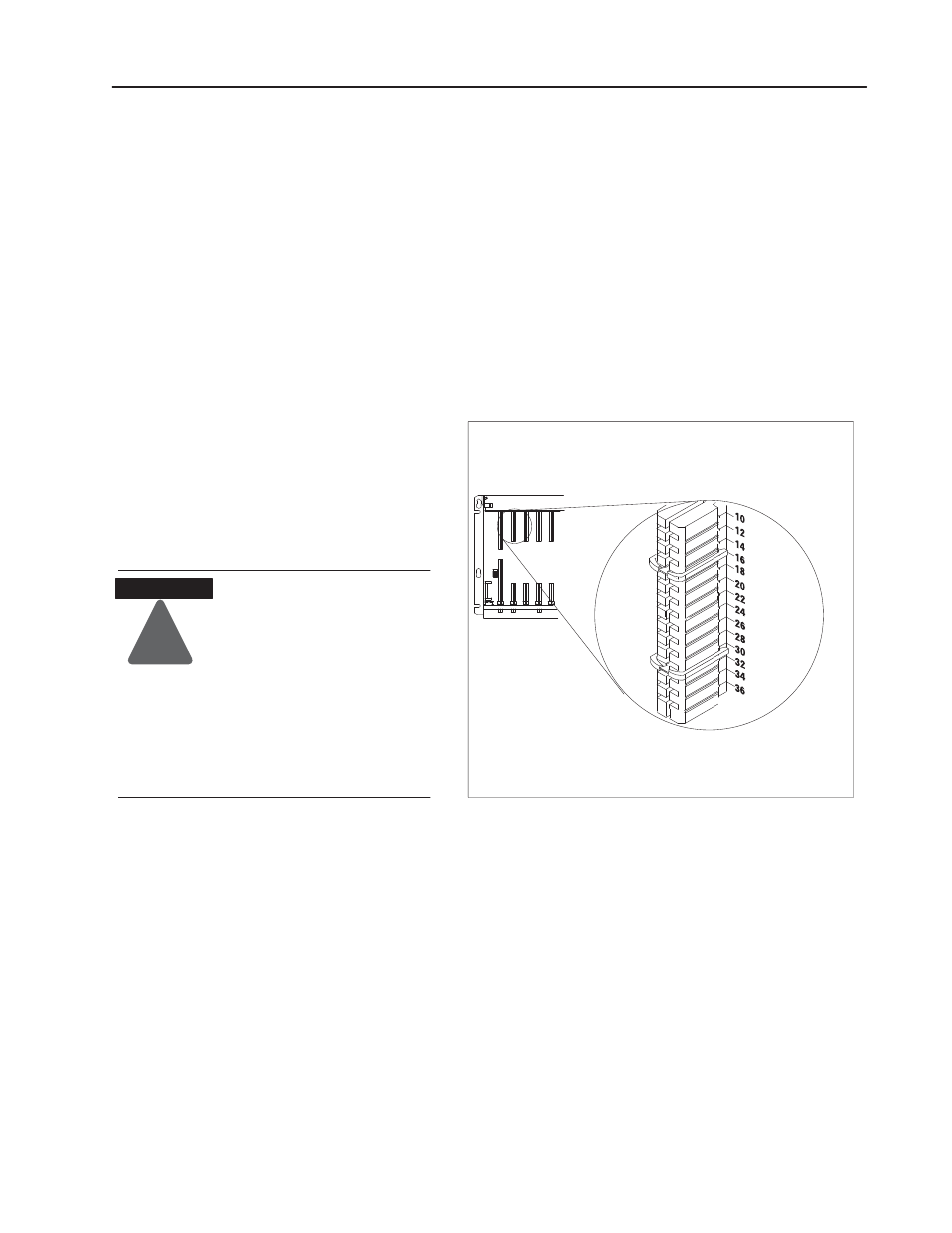
Key the Backplane
Connector
Place your module in any slot in the chassis
except the leftmost slot which is reserved for
processors or adapters.
Observe the following
precautions when inserting or
removing keys:
•
insert or remove keys with
your fingers
•
make sure that key placement
is correct
Incorrect keying or the use of a
tool can result in damage to the
backplane connector and
possible system faults.
!
ATTENTION
Position the keying bands in the backplane connectors to correspond to
the key slots on the module. Place the keying bands:
between 14 and 16
between 30 and 32
You can change the position of these bands if
subsequent system design and rewiring makes
insertion of a different type of module necessary.
Upper
Connector
11022ĆI
I/O chassis
Calculate Power Supply
Requirements