Installing or changing a fuse in the 1794-tbnf – Rockwell Automation 1794-OW8_OW8K_OW8XT Flex I/O 8 Output Relay Module User Manual
Page 4
4
Publication 1794-IN019H-EN-P - January 2011
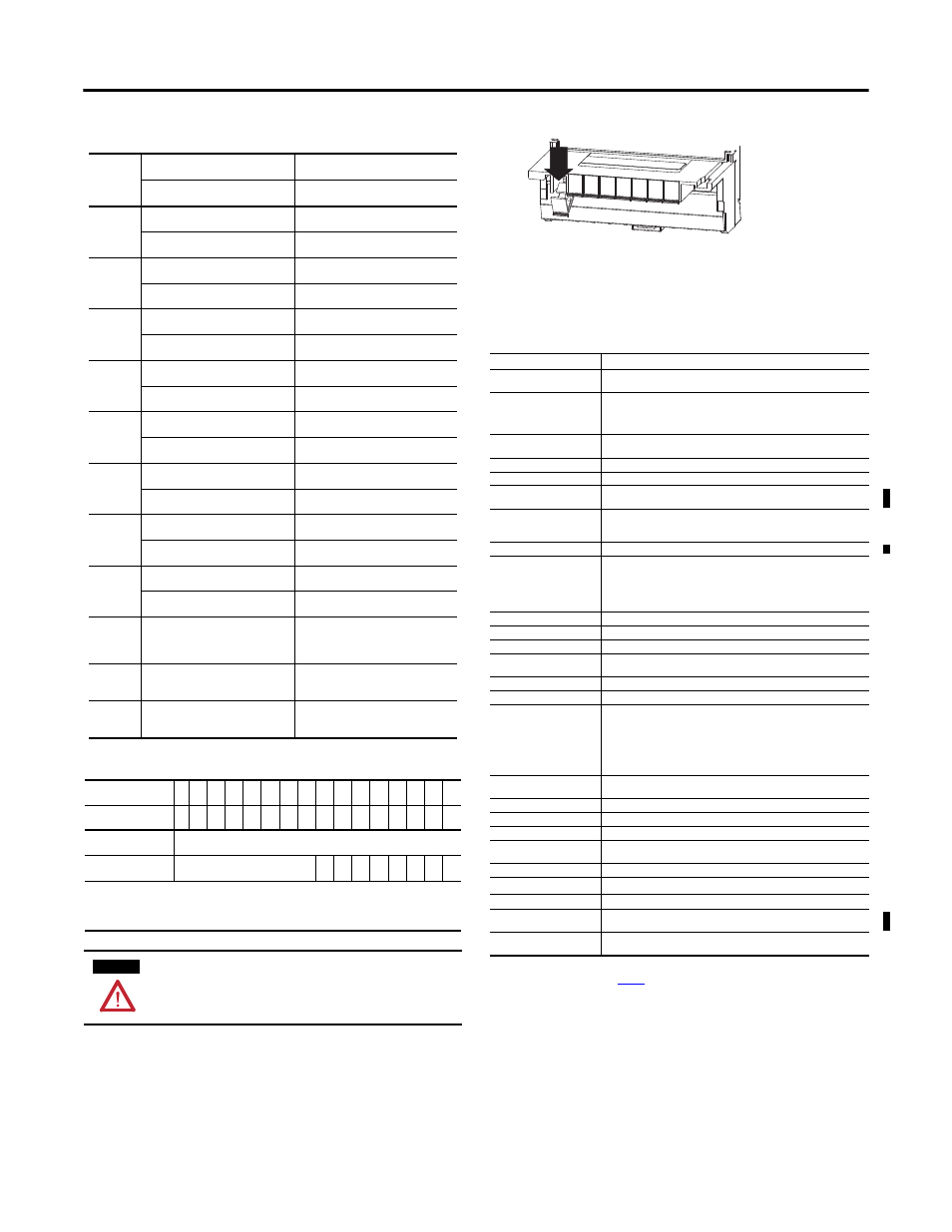
Installing or Changing a Fuse in the 1794-TBNF
This terminal base unit has fuse holders for 5 x 20 mm fuses on each of the 8
even-numbered I/O terminals 0…14 (row B). To install or change a fuse:
1.
Press the fuse holder down toward the terminal strip.
2.
If replacing a fuse, remove the fuse from the fuse holder.
3.
Insert a known good 5 x 20 mm fuse (Littelfuse pt. no. 239003, 3.0 A,
250V AC slow-blow) into the fuse holder.
4.
Replace the fuse holder by rotating the fuse holder back to vertical until it
snaps into the locked position.
Wiring Connections for the 1794-OW8, 1794-OW8K, 1794-OW8XT
Output
Channel
1794-TB2, 1794-TB3, 1794-TB3S
1794-TBN, 1794-TBNF
Output Terminal
Output Terminal
0
A-0
B-0
A-1
C-1
1
A-2
B-2
A-3
C-3
2
A-4
B-4
A-5
C-5
3
A-6
B-6
A-7
C-7
4
A-8
B-8
A-9
C-9
5
A-10
B-10
A-11
C-11
6
A-12
B-12
A-13
C-13
7
A-14
B-14
A-15
C-15
A-(even) = one contact of the relay
A-(odd) = the other contact of the relay
B-(even) = one contact of the relay
C-(odd) = the other contact of the relay
+24V DC
C-34…C-51 (1794-TB3, 1794-TB3S)
C-34 and C-51 (1794-TB2)
C-34 and C- 51
-24V DC
(RET)
B- 16…B-33
B-16 and B-33
Image Table Memory Map
Dec.
15
14
13
12
11
10
09
08
07
06
05
04
03
02
01
00
Oct.
17
16
15
14
13
12
11
10
07
06
05
04
03
02
01
00
Read Word
Not used - reserved
Write Word
Not used - set to 0
O7 O6 O5 O4 O3 O2 O1 O0
Where:
O = Output number (O0 corresponds to output 0, O1 corresponds to output 1,
and so on)
When bit = 0, output 0 is off; when bit=1, output 0 is on.
WARNING
The 1794-TBNF and 1794-TBNFK are not approved for use in Class I
Division 2 applications.
General Specifications
Attribute
Value
Outputs per module
1 group of 8 Form A isolated (normally open)
electromechanical relays
Module location
Mounts on 1794-TB2, 1794-TB3, 1794-TB3S, 1794-TBN and 1794-TBNF
Terminal Base Units.
When using 1794-TBNF terminal base unit, use 3.0 A, 250V AC slow-blow
fuses (Littelfuse pt. no. 239003)
Off-State leakage
current (max at 240V AC)
1.0 mA through snubber circuit
Minimum contact load
100
μ
A @ 100 mV DC
Flexbus current
5V DC, 35 mA
Supply voltage
24V DC, 125 mA (1794-OW8, 1794-OW8K)
19.2...31.2V DC, 126 mA (1794-OW8XT)
Relay Contact
250V AC, 2 A, 50/60Hz, Resistive;
120/240V AC, 50/60Hz,1800V A Make, 180V A Break;
5…30V DC, 2 A, Resistive;
Pilot Duty Rating
R150, 5...30V DC, 28V A not to exceed 1 A below 28V DC
Output signal delay
OFF to ON
10 ms max (time from valid output on signal to relay energization by
module)
ON to OFF
10 ms max (time from valid output off signal to relay deenergization by
module)
Initial contact resistance
30 m
Ω
Switching frequency
1 operation/3 s (0.3Hz at rated load) max
Bounce time
1.2 ms (mean)
Expected life of
electrical contacts
100,000 operations, min @ rated loads
Thermal dissipation
18.8 BTU/hr max
Power dissipation
5.5 W
Isolation voltage
250V (continuous), Basic Insulation Type, relay to relay, relay to backplane,
and relay to power
50V (continuous), Basic Insulation Type, power to backplane
Type tested at 1500V AC for 60 s, relay to relay, all combinations.
Type tested at 3250V DC for 60 s, relay to backplane and relay to power
Type tested at 720V DC for 60 s, power to backplane.
Fusing
Fusing of outputs is recommended. Use 3.0 A, 250V AC slow-blow fuses
(Littelfuse pt. no. 239003).
Indicators
8 yellow status indicators
Keyswitch position
9
Terminal screw torque
Determined by installed terminal base
Dimensions (with module
installed)
94H x 94W x 69D mm
(3.7H x 3.7W x 2.7D inch)
Enclosure
None (open-style)
Wiring category
(1)
(1)
Use this Conductor Category information for planning conductor routing. Refer to Industrial Automation Wiring and
Grounding Guidelines, publication
2 - on signal ports
Wire size
Determined by installed terminal base
IEC temp code
T4 (1794-OW8XT)
T5 (1794-OW8, 1794-OW8K)
North American temp code
T4 (1794-OW8XT)
T5 (1794-OW8, 1794-OW8K)
Press down to open
45282