Installation, Fiber optic connection, Power supply – Rockwell Automation 1785-TR10BF Optical Transceiver Installation Instructions User Manual
Page 3: Sqe test setting, Connecting devices, For additional information
1785-5.19 - January 1999
Optical Transceiver
3
Installation
Fiber Optic Connection
Two BFOC sockets are available for connecting the 1785-TR10BF
transceiver to a fiber optic segment. One connection is used for transmitting
and one for receiving data over the fiber optic cable.
The maximum length of the fiber optic segment is
•
2000 m for 50/125 fiber
•
3000 m for 62.5/125 fiber
Power Supply
The operating voltage (+12 V) is taken from the connected device via the
15-pin sub-D socket of the AUI interface.
SQE Test Setting
The slide switch on the top of the transceiver case is used to activate and
deactivate the SQE test. Before placing the transceiver in operation, you
should check to see whether the connected device requires the SQE test to
be on or off. As delivered from the factory, the SQE test is on.
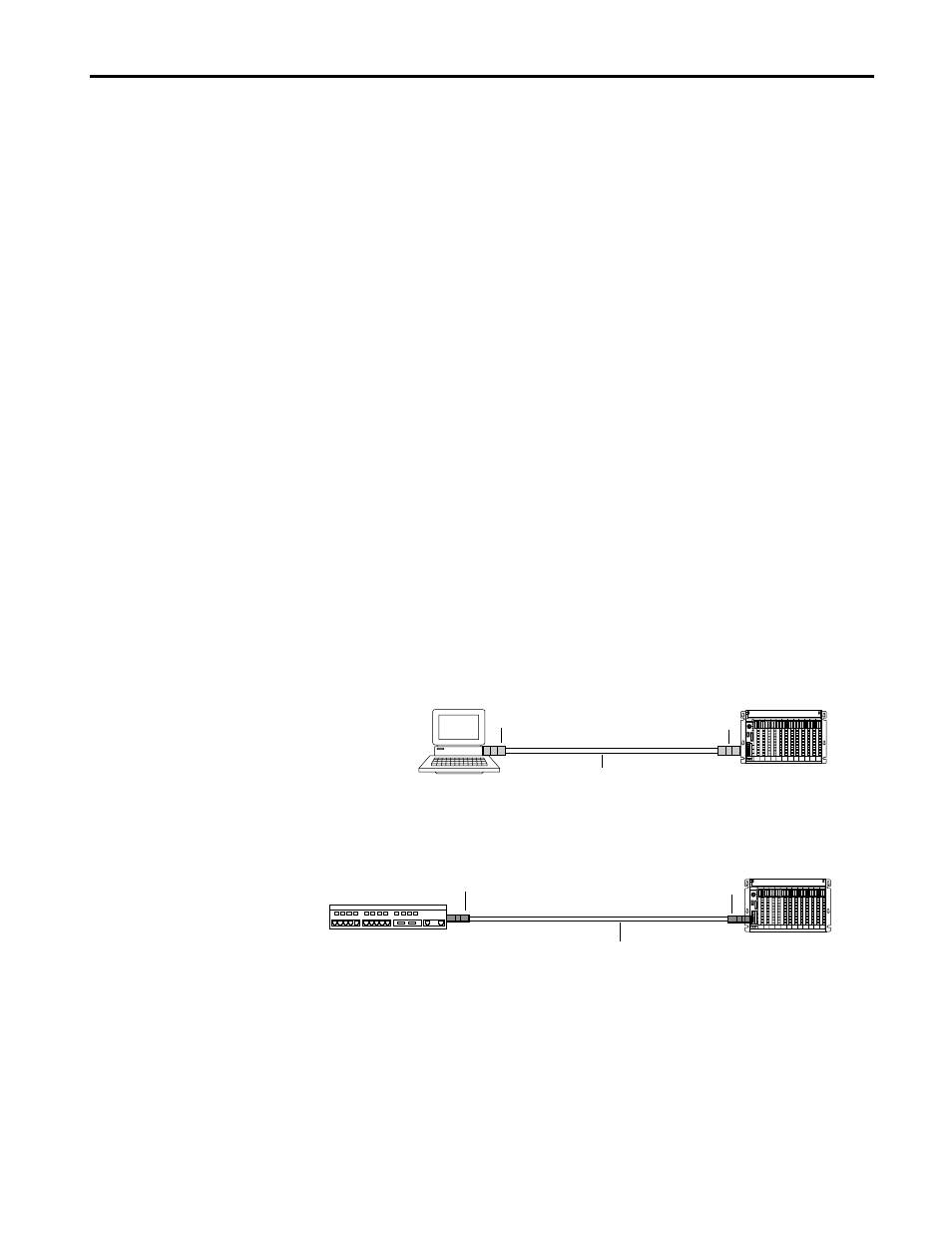
Connecting Devices
For Additional Information
For standards information, go to
http://www.ieee.org/
. To download a .PDF
copy of this publication, go to
http://www.theautomationbookstore.com/
.
Connecting two devices
PC
PLC5E
1785-TR10BF
1785-TR10BF
Fiber optic cable 2000 meters (50/125 microns)
3000 meters (62.5/125 microns) max.
Connecting to
a fiber optic interface hub
PLC5E
Hub
1785-TR10BF
1785-TR10BF
Fiber optic cable 2000 meters (50/125 microns)
3000 meters (62.5/125 microns) max.