Install your controlnet, Mounting dimensions, Mount on a din rail – Rockwell Automation 1794-ACN15_ACN15K_ACNR15_ACNR15XT, Series D FLEX I/O ControlNet Adapter Modules User Manual
Page 3: Mount on a panel or wall, Mount or replace the adapter on an existing system
FLEX I/O ControlNet Adapter Modules 3
Publication 1794-IN128E-EN-P - March 2011
Install Your ControlNet
Mounting Dimensions
The module has the following mounting dimensions.
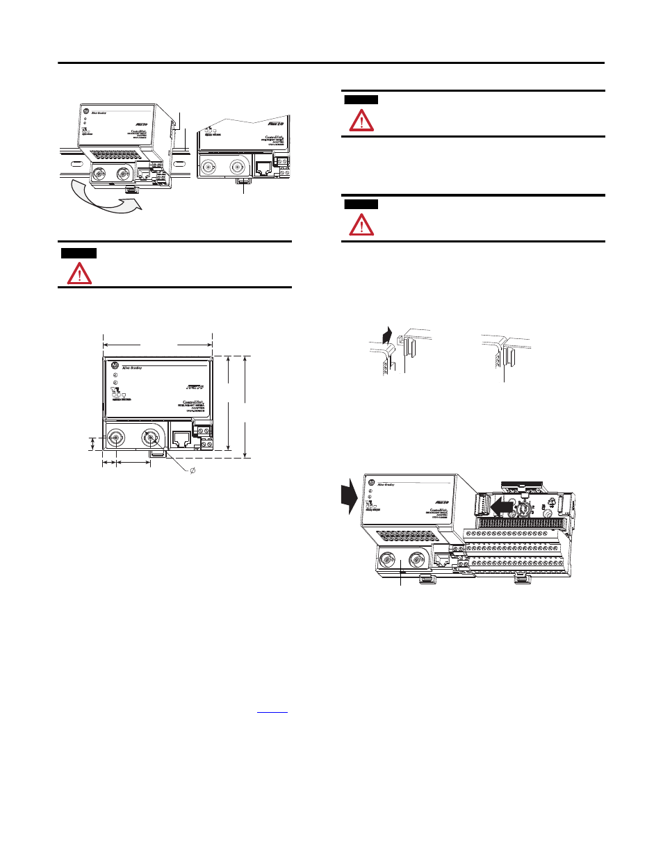
Mount on a DIN Rail
1. Position the ControlNet adapter module (A) on an IEC standard (35 x 7.5
x 1 mm) top-hat DIN rail, Allen-Bradley part number 199-DR1; 46277-3;
EN50022 (B), at a slight angle.
2. Hook the lip on the rear of the adapter onto the top of the DIN rail, and
rotate the adapter module onto the rail.
3. Press the adapter module down onto the DIN rail until flush. Locking tab
C snaps the adapter into position and locks it onto the DIN rail.
4. If the adapter module does not lock in place, use a screwdriver or similar
device to move the locking tab down while pressing the adapter module
flush onto the DIN rail, and release the locking tab to lock the adapter
module in place. If necessary, push up on the locking tab to lock.
5. Connect the adapter wiring as shown in the section, Connecting Wiring.
Mount on a Panel or Wall
If mounting this adapter to a panel or wall, refer to publication
, Panel
Mounting Kit, Cat. No. 1794-NM1.
Mount or Replace the Adapter on an Existing System
1. Disconnect any wiring jumpered to the adjacent terminal base.
2. Disconnect the BNC connector(s) from the front of the adapter.
3. Open the module latching mechanism and remove the module from the
base unit to which the adapter will be attached.
4. Push the FlexBus connector toward the right side of the terminal base to
unplug the backplane connection.
5. Release the locking tab and remove the adapter module.
Before installing the new adapter, notice the notch on the right rear of the
adapter. This notch accepts the hook on the terminal base unit. The notch
is open at the bottom. The hook and adjacent connection point keep the
terminal base and the adapter tight together, reducing the possibility of a
break in communication over the backplane.
6. Complete the adapter mounting as shown below.
Push down and in at the same time to lock the adapter to the DIN rail.
If the adapter does not lock in place, use a screwdriver or similar device to
move the locking tab down while pressing the adapter flush onto the DIN
rail, and release the locking tab to lock the adapter module in place. If
necessary, push up on the locking tab to lock.
When the adapter is locked onto the DIN rail, gently push the FlexBus
connector into the adapter to complete the backplane
7. Reinstall the module in the adjacent terminal base unit.
ATTENTION
During mounting of all devices, be sure that all debris (for example,
metal chips, wire strands) is kept from falling into the module. Debris
that falls into the module could cause damage on power up.
0
1
2
3
4
5
6
7 8
9
0
1
2
3
4
5
6
7 8
9
X10
X1
45086
A
B
C
0
1
2
3
4
5
6
7 8
9
0
1
2
3
4
5
6
7 8
9
X10
X1
94
(3.7)
80.4
(3.16)
87.4
(3.44)
10.7
(0.42)
11.44
(0.45)
29.48
(1.16)
15
(0.59)
45091
HxWxD:
87.4 x 94 x 92 mm
(3.44 x 3.7 x 3.6 in.)
1794-ACNR15
shown
Millimeters
(inches)
WARNING
If you connect or disconnect the communications cable with power applied to
this module or any device on the network, an electrical arc can occur. This could
cause an explosion in hazardous location installations.
Be sure that power is removed or the area is nonhazardous before proceeding.
WARNING
If you insert or remove the module while backplane power is on, an electrical arc
can occur. This could cause an explosion in hazardous location installations.
Be sure that power is removed or the area is nonhazardous before proceeding.
0
1
2
3
4
5
6
7 8
9
0
1
2
3
4
5
6
7 8
9
X10
X1
45087
C