Iv. conversion module wiring diagram – Rockwell Automation 1492-CM800-LD010 Field Wire Conv. Module for Modicon B827-032 to 1756-IB32 User Manual
Page 2
(2)
10000021893
(Version 00)
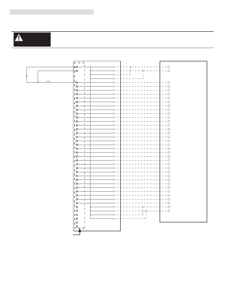
IV. Conversion Module Wiring Diagram
The following diagram shows the connections from the existing B827-032 swing-arm, through the conversion module, 1492
cable and to the 1756-IB32 input module. The diagram can be used as an aid in possible system troubleshooting.
1756-IB32
1492-CABLE003Z
1492-CM800-LD010
Conversion: B827-032 to 1756-IB32 with 1492-CM800-LD010
B827-032 Swing Arm
Conversion Module Installation and Application Considerations
The input delay times for the B827-032 module versus 1756-IB32 module are as follows:
B827-032
1756-IB32
a) Off-to-On Delay
0.4ms
0.38ms (plus selectable filter)
b) On-to-Off Delay
1ms
0.42ms (plus selectable filter)
The B827-032 modules provided a fuse for input power. The 1756-IB32 is NOT fused.
Refer to your B827-032 and 1756-IB32 Installation Manual wiring schematics and diagrams for more details.
[Reference Doc: 41170-760 (Version 03)]
1
2
3
4
1
5
21
6
2
7
22
8
3
9
23
10
4
11
24
12
5
13
25
6
15
26
16
7
17
27
18
8
19
28
20
14
9
21
29
22
10
23
30
24
11
25
31
26
12
27
32
28
13
29
33
30
14
31
34
32
15
33
35
16
35
36
36
17
37
19
38
39
40
34
Input 1
Input 17
Input 2
Input 18
Input 3
Input 19
Input 4
Input 20
Input 5
Input 21
Input 6
Input 22
Input 7
Input 23
Input 8
Input 24
Input 9
Input 25
Input 10
Input 26
Input 11
Input 27
Input 12
Input 28
Input 13
Input 29
Input 14
Input 30
Input 15
Input 31
Input 16
Input 32
37
38
39
40
Not Used
Not Used
Not Used
Not Used
20
Common
18
GND-0
IN-0
1
IN-16
19
IN-1
2
IN-17
20
IN-2
3
IN-18
21
IN-3
4
IN-19
22
IN-4
5
IN-20
23
IN-5
6
IN-21
24
IN-6
7
IN-22
25
Black
White
Red
Green
Orange
Blue
White/Black
Red/Black
Green/Black
Orange/Black
Blue/Black
Black/White
Red/White
Green/White
Blue/White
Black/Red
White/Red
Orange/Red
Blue/Red
Red/Green
IN-7
8
GND-1
36
IN-23
26
IN-8
9
IN-24
27
IN-9
10
IN-25
28
IN-10
11
IN-26
29
IN-11
12
IN-27
30
IN-12
13
IN-28
31
IN-13
14
IN-29
32
IN-14
15
IN-30
33
Orange/Green
Black/White/Red
White/Black/Red
Red/Black/White
Green/Black/White
Orange/Black/White
Blue/Black/White
Black/Red/Green
White/Red/Green
Red/Black/Green
Green/Black/Orange
Orange/Black/Green
Blue/White/Orange
Black/White/Orange
White/Red/Orange
Orange/White/Blue
IN-15
16
IN-31
34
17
White/Red/Blue
Black/White/Green
White/Black/Green
Red/White/Green
35
GND-0
GND-1
Not Used
Not Used
18
+ VDD
+
-
There are several key application considerations and system specifications (bottom of drawing) when using
these components (conversion module, cable and output module). Read and understand these consider-
ations before installation.
WARNING