Replacing the shunt power connector plug, Inserting keys into the system module connectors – Rockwell Automation 1394C-SJT_CONN-KEY Installing Your Power Connector Key Kit User Manual
Page 5
Installing Your 1394C Power Connector Key Kit
5
Publication 1394-IN023A-EN-P — July 2000
Replacing the Shunt Power Connector Plug
To replace the shunt power connector plug:
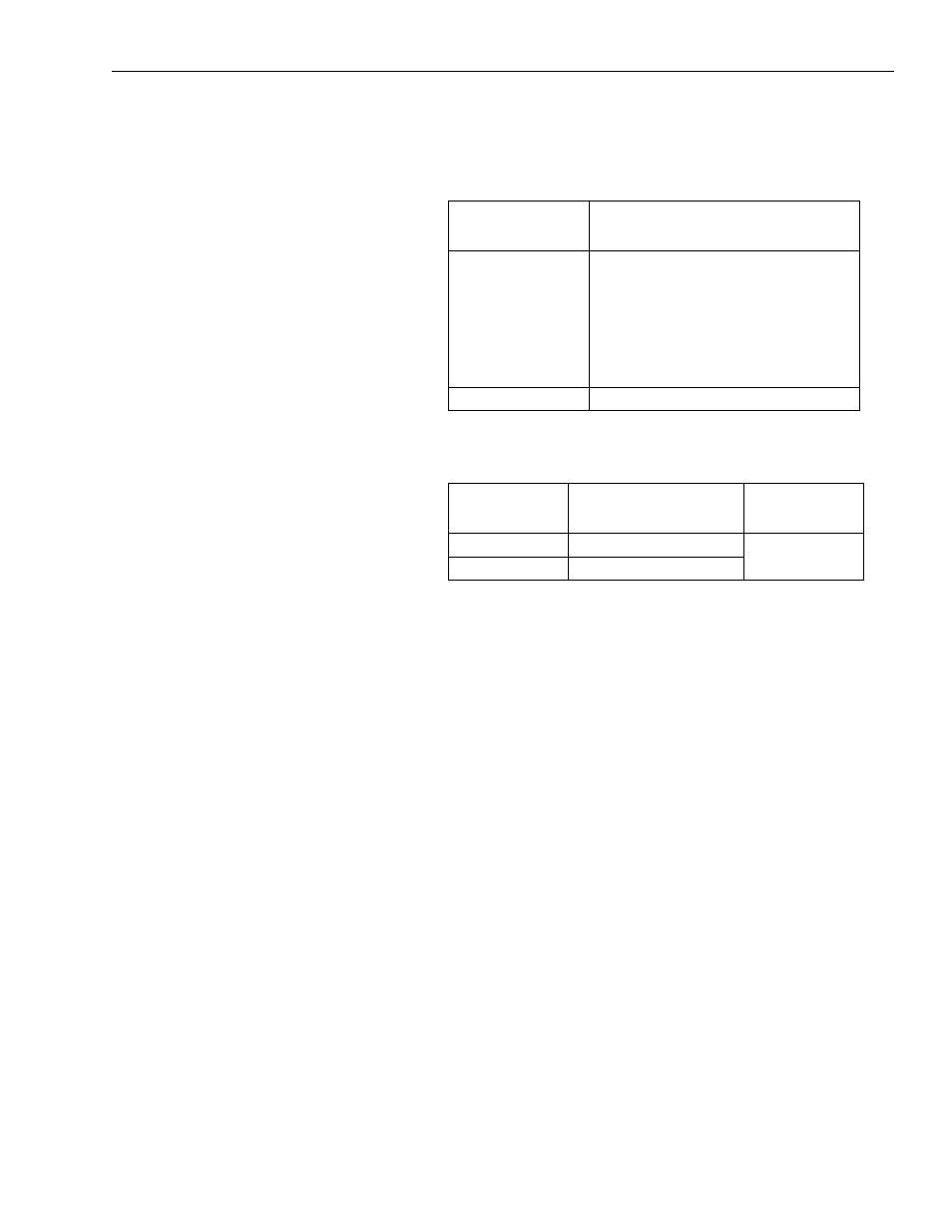
1.
2. Remove jumper from the replacement connector plug (supplied
in the kit) and insert the wires as shown in the table below.
3. Gently pull on each wire (or jumper) and make sure it does not
come out of its terminal(s). Re-insert and tighten any loose wires.
Inserting Keys into the System Module Connectors
1. Insert a key into the beveled slot above the input power connector
terminal on the far right. This terminal lines up with the connector
plug terminal labeled PE (refer to Figure 3 for key placement).
2. Insert a key into the beveled slot above the shunt power connector
terminal on the far left. This terminal lines up with the connector
plug terminal labeled COL (refer to Figure 3 for key placement).
If the 1394-SR10A
shunt resistor is:
Then:
Installed
1. Loosen the screws in the old shunt
power connector plug and remove
the wires from each terminal
(refer to Figure 2 for connector
location).
2. Go to main step 2.
Not installed
Go to main step 3.
Insert the wires
labeled:
Into the connector
plug terminals labeled:
Tighten to this
torque value:
COL
COL
0.56-0.62 N-m
(5.0-5.6 lb-in.)
DC+
DC+