Functional diagram, Front side and user elements, L3 l2 l1 – Rockwell Automation 1606-XLE960DX-3N Power Supply Reference Manual User Manual
Page 9
All parameters are specified at 24V, 40A, 3x480Vac, 25°C ambient and after a 5 minutes run-in time, unless noted otherwise.
Rockwell Automation Publication 1606-RM024A-EN-P — April 2014
9
Bulletin 1606 Switched Mode Power Supplies
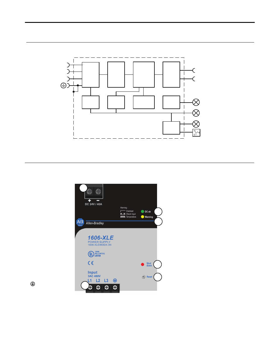
10. Functional Diagram
Fig. 10-1 Functional diagram
+
-
Active
Transient
Blocker
Input
Filter
Input
Rectifier
Reset
Output
Voltage
Monitor
Over-
Voltage
Protection
Output
Power
Manager
Temp.
Shut-
down
Input
Voltage
Monitor
L3
L2
L1
Semi-
regulated
Power
Converter
Output
Filter
DC-ok
LED
Warning
LED
Shut-down
LED
11. Front Side and User Elements
Fig. 11-1 Front side of 1606-XLE960DX-3N
A. Output Terminals
Large screw terminal
+ Positive output
- Negative (return)
output
See section 12
“Terminals and
Wiring” to choose
appropriate wire size.
B. Input Terminals
Screw terminals
L1, L2, L3:
Line inputs
PE (Protective
Earth) input
C. DC-ok LED (green)
Indicates a normal operation. The LED is on
if the output voltage is higher than 21.6V.
D. Warning LED (yellow)
- A steady-state light indicates an output
current higher than the nominal current
and that the internal shutdown timer is
running.
- A double flash indicates a phase-loss or
too low / too high input voltage.
(1606-XLE960DX-3N:
< 3x400Vac or > 3x560Vac)
- A fast flash warns of an impending
temperature shut-down. A shut-down
can be expected within 10 minutes, if
the ambient temperature or the load
current stays constant.
E. Shut-down LED (red) and reset button F.
The red LED flashes when the device has
shut down. Pressing the reset button or
cycling the input power (10s required)
initiates a restart. If the fault has been
cleared the device will operate normally.
A
B
C
D
E
F