E - doc, Handle installation, Right hand-flange left hand-flange – Rockwell Automation 1494V Flange Operated Circuit Breaker Kits (125A / 150A / 250A / 400A) User Manual
Page 2
CIRCUIT BREAKER AND ACCESSORY
INSTALLATION INSTRUCTION SHEET
1
1013923
42052-074
OF
N/A
N/A
N/A
REVISION
AUTHORIZATION
DR.
CHKD.
APPD.
DATE
DATE
DATE
E - DOC
LOCATION: MILWAUKEE, WISCONSIN U.S.A.
B-vertical.ai
DWG.
SIZE
SHEET
B
1
2
3
4
5
6
7
8
A
B
C
D
E
F
G
H
REFERENCE
DIMENSIONS APPLY BEFORE
SURFACE TREATMENT
(DIMENSIONS IN INCHES)
TOLERANCES UNLESS
OTHERWISE SPECIFIED
.XX:
.XXX:
ANGLES:
42052
THIS DRAWING IS THE PROPERTY OF
ROCKWELL INTERNATIONAL CORPORATION
OR ITS SUBSIDIARIES AND MAY NOT BE COPIED,
USED OR DISCLOSED FOR ANY PURPOSE
EXCEPT AS AUTHORIZED IN WRITING BY
ROCKWELL INTERNATIONAL CORPORATION
---------------
---------------
---------------
---------------
---------------
---------------
2
7
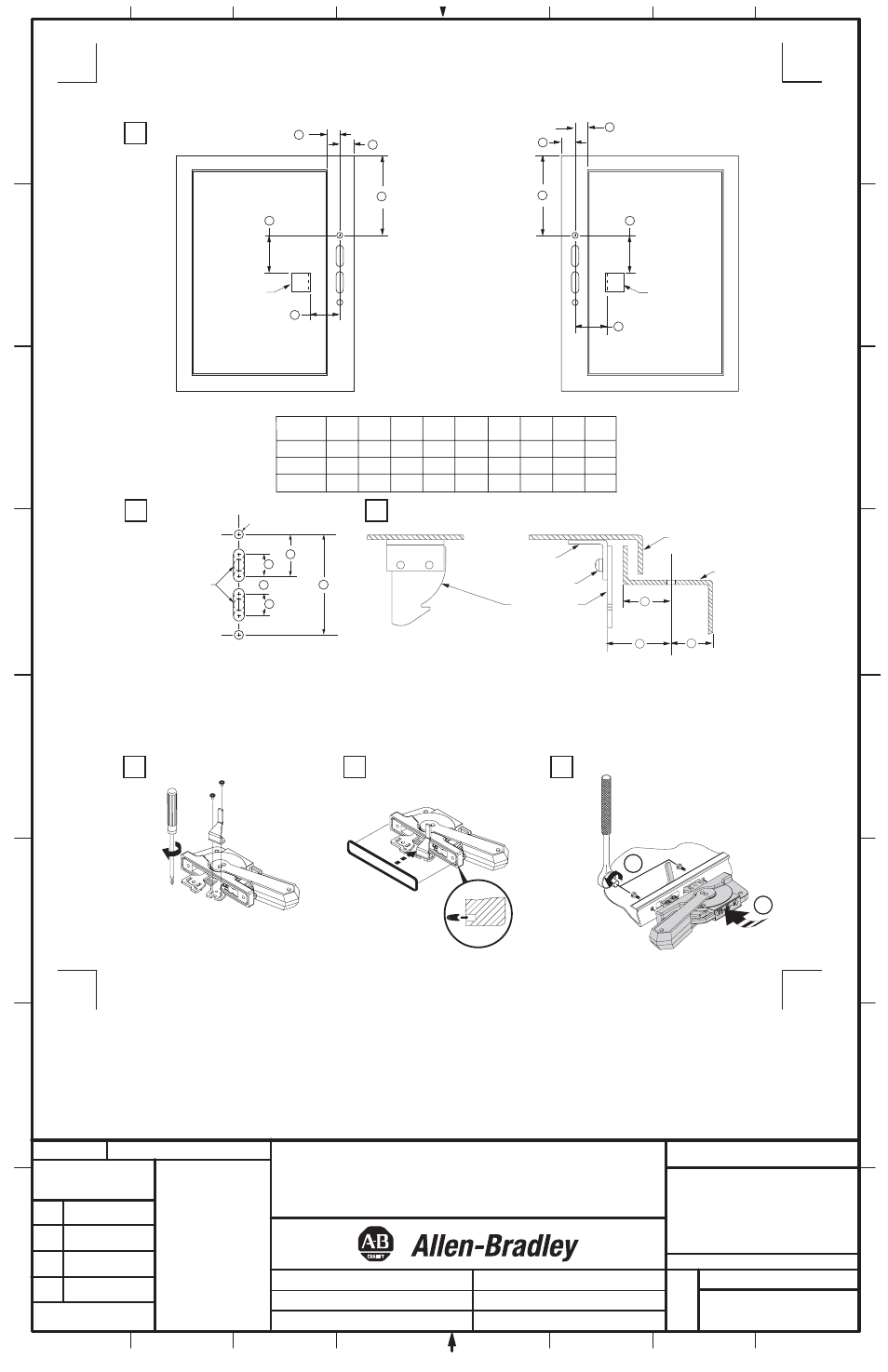
Handle Installation
4
1
3
7-11 lb-in
Door Catch
Mounting
Bracket
To make slot drill
(3) 1/2" diameter holes
and remove burrs
E
D
Door Catch
Mounting
Bracket
Locate Handle
Right Hand-Flange
Left Hand-Flange
(2) .265 Dia. Holes
Drill Handle Holes
D
B
C
A
C
B
A
E
5
2
F
G
H
J
H
Locate Door Catch
Install Defeater Lever
Install Gasket
6
Install Handle to Flange
(2)
Notes:
A) Enclosures with a Flange Thickness less than 3/16" use dimensions above.
B) Enclosures with a Flange Thickness 3/16" and greater use dimensions in Mounting Kit 1494V-H3.
C) Multi-Door Enclosures use dimensions in Channel Support Kit 1494V-H4, if handle is mounted atop channel.
D) The door catch mounting bracket is provided with projections for welding; however, holes can be drilled in the bracket using the
projections for locating hole centers. After proper location, use the bracket as a template and drill corresponding holes in the
enclosure door. Fasten the bracket with hardware supplied by user. If properly assembled, the hardware should not be accessible for
tampering with by unauthorized personnel.
1 - 5/8"
D
1 - 5/8"
1 - 5/8"
E
2 - 11/32"
2 - 11/32"
2 - 11/32"
F
4 - 11/16"
4 - 11/16"
4 - 11/16"
G
1 - 9/16"
1 - 9/16"
1 - 9/16"
H
1"
1"
1"
J
7/8"
7/8"
7/8"
1 - 3/32"
C
(max)
1 - 3/32"
1 - 3/32"
B
(min)
29/32"
29/32"
29/32"
A
(min)
3 - 1/2"
10 - 29/32"
13 - 3/32"
FRAME
SIZE
125A, 150A
400A
250A
2
23-37 lb-in
1
C
B
Door Catch
Mounting Bracket
Door Catch
30 lb-in
Enclosure Door
D
Enclosure
Base