Iv. conversion module wiring diagram (continued) – Rockwell Automation 1492-CM800-LA002 Field Wire Conv. Module for Modicon B877-111 to 1756-IF16 User Manual
Page 3
(3)
10000021831
(Version 00)
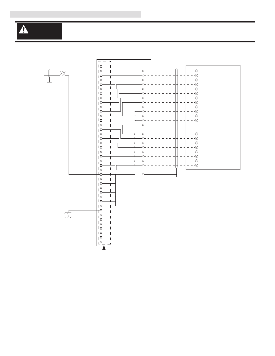
IV. Conversion Module Wiring Diagram (Continued)
Conversion: B877-111 to 1756-IF16 (Single Ended Voltage) with 1492-CM800-LA002
Conversion Module Installation and Application Considerations
T1 The B875-111 indicated differential inputs. When it was configured for single ended inputs, it was referred to as a B877-111.
SHIELD GROUNDING: For single ended voltage analog inputs both the B877-111 and 1756-IF16 recommend grounding the field wiring shield at
the analog source/device. As such, no shield ground modifications should be requried. The pre-wired cable used between the 1492-CM800-LA002
and the 1756-IF16 [1492-ACABLE003UA] provides a shield ground lug to ground the shield at the 1756 ControlLogix chassis, this must be
connected.
The B877-111 recommended placing jumpers from UNUSED to USED analog input channels. These jumpers can be removed if desired. They
are not required on the 1756-IF16, but they will not impact its operation (in voltage mode) if they are left connected.
The B77-111 analog input ranges were configured by DIP switches on the module. The appropriate range for the 1756-IF16 is configured by
software.
This design assumes that all inputs on the B877-111 were connected to voltage transmitters. If there was a mix of current and voltage transmitters,
then modification of pre-wired cable will need to occur at the 1756-IF16 terminal block. Refer to the 1756-IF16 Installation Manual for modification
details.
CASE GROUND: If connected, remove this wire from the B877-111 terminal block, as it serves no purpose for the 1756-IF16.
Refer to your B877-111 and 1756-IF16 Installation and User Manuals for additional information concerning comparisons of module wiring,
features, and configuration details.
[Reference Doc: 41170-785
(Version 03)]
There are several key application considerations and system specifications (bottom of drawing) when
using these components (conversion module, cable and output module). Read and understand these
considerations before installation.
WARNING
1492-CM800-LA002 Conversion Module
De-energize and lockout any and all power to all I/O field devices connected to the Modicon 800 I/O
housing, and the power to the 800 I/O housing itself. Ensure all power is de-energized and locked out to
any device in the control cabinet where the conversion is to be performed. Ensure work is performed by
qualified personnel.
WARNING
3
7
8
11
12
15
16
5
9
13
17
25
29
Input 7
Input 8
Input 3
Input 5
Input 4
Input 6
3
2
1
14
15
16
17
18
4
6
8
10
19
12
13
25
24
23
22
20
21
+
-
4
Input 1
Input 2
2
6
10
14
23
27
28
31
32
35
36
Input 15
Input 16
Input 11
Input 13
Input 12
Input 14
24
Input 9
Input 10
22
26
30
34
SH
33
37
Input 1,2 Return
1
40
18
19
20
21
38
39
Voltage Reference -
Voltage Reference +
Not Used
Not Used
Not Used
Not Used
Case Ground
Case Ground
Not Used
Not Used
Not Used
Not Used
Not Used
Not Used
Not Used
Not Used
Input 3,4 Return
Input 5,6 Return
Input 7,8 Return
Input 9,10 Return
Input 15,16 Return
Input 13,14 Return
Input 11,12 Return
2
IN-0
IN-1
4
IN-2
6
IN-3
8
IN-4
12
IN-5
14
IN-6
16
IN-7
18
RTN
10
RTN
27
RTN
28
IN-9
22
IN-8
20
IN-11
26
IN-10
24
IN-15
36
IN-14
34
Red
RTN
9
Brown
Black
White
White/Black
White/Brown
White/Red
White/Orange
Orange
Yellow
Green
Blue
IN-13
32
IN-12
30
Violet
Gray
White/Black/Brown
White/Gray
White/Violet
White/Blue
White/Yellow
White/Green
B877-111 Swing Arm
1756-IF16
1492-CM800-LA002
1492-ACABLE003UA