I/o wiring data – Rockwell Automation 1492-IFMxxxx Sensor Interface Modules User Manual
Page 3
(3)
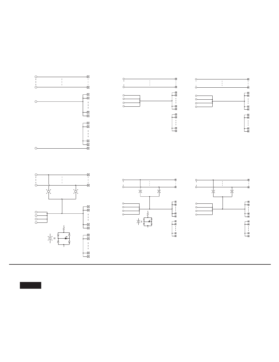
Pinout
Brochage
Anschlußbelegung
Disposizione
dei piedini
Esquema de pins
1492-IFM20F-3 (Series B)
3
18
C1
C16
B1
B2
1
20
B17
B18
A1
A2
A16
A17
A18
1492-IFM20D24-3
3
18
C1
C16
B1
B2
2
B17
B18
A1
A2
A17
A18
1
19
20
1492-IFM40F-3
5
35
C1
C16
B1
B2
B17
B18
A1
A2
A17
A18
6
36
C1
C16
B1
B2
B17
B18
A1
A2
A17
A18
TB1
TB2
(odd)
(even)
3
1
37
39
4
2
38
40
1492-IFM40D24-3
5
35
C1
C16
B1
B2
3
B17
B18
A1
A2
A17
A18
1
37
39
6
36
C1
C16
B1
B2
B17
B18
A1
A2
A17
A18
TB1
TB2
4
2
38
40
(odd)
(even)
LED Circuit
Circuit du LED
LED-Stromkreis
Circuito del LED
LED Circuit
Circuit du LED
LED-Stromkreis
Circuito del LED
Odd
Impair
Ungerade
Dispari
Impar
Even
Pair
Gerade
Pari
Par
Odd
Impair
Ungerade
Dispari
Impar
Even
Pair
Gerade
Pari
Par
I/O Wiring Data
NOTICE
Wiring information for your I/O module, AIFM module and cable (e.g. wiring diagram and pinouts)are available online at www.rockwellautomation.com/en/e-tools.
To obtain information follow this procedure.
1) In the Catalog Number BOX at the above online site type in the catalog number of the IFM, AIFM, etc. module you are using and click on Submit.
2) At the next screen displayed, click on the Modify key (lower left of screen).
3) Click on the areas that indicate NO SELECTION and enter your specific configuration information (e.g. I/O platform, I/O MODULE, ETC.).
NOTE: To obtain the wiring diagram, you must select th Pre-Wired Cable Connector selection.
4) Configure your 1492 cable by filing in the NO SELECTION areas.
5) Click on the ACCEPT key for the configured 1492 cable. At the next screen click on ACCEPT for the 1492 module.
6) The next screen (Configuration Results) displays the results of your specific configuration. The "supplementary Documents" column contains I/O wiring information
for the configuration (e.g. I/O Wiring Diagrams).
PN-23245
DIR 40063-259 (Version 11)