Rockwell Automation 1203-FB1 FLEX I/O SCANport Base User Manual
Page 4
FLEX I/O SCANport
t
Base Installation Instructions
1–4
1203-5.7ML- April 1996
6. Press the terminal base down onto the DIN rail until flush. The
locking lever D snaps into position and locks the terminal base
to the DIN rail.
7. If the terminal base does not lock in place, use a screwdriver or
similar device to move the locking lever down, press the
terminal base flush with the DIN rail, and release the locking
lever to lock the base in place.
8. Gently push the female flexbus connector C into the adjacent
terminal base or adapter male connector to complete the flexbus
connections.
9. For specific wiring information, refer to the installation
instructions for the module you are installing in this terminal
base unit.
10.Repeat the above steps to install the next terminal base.
!
ATTENTION:
The 1203 flex modules that use this base may
require up to twice the adapter power supply current of standard
flex modules. When installing flex modules, you can use a
maximum of four 1203 modules with any flex adapter. As a
general rule, each 1203 module requires the power capacity of two
of the standard flex modules, so you cannot install as many
standard modules as you normally would when using the 1203
modules. Refer to the following chart to determine the number of
1203 and standard modules that may be installed together in your
system.
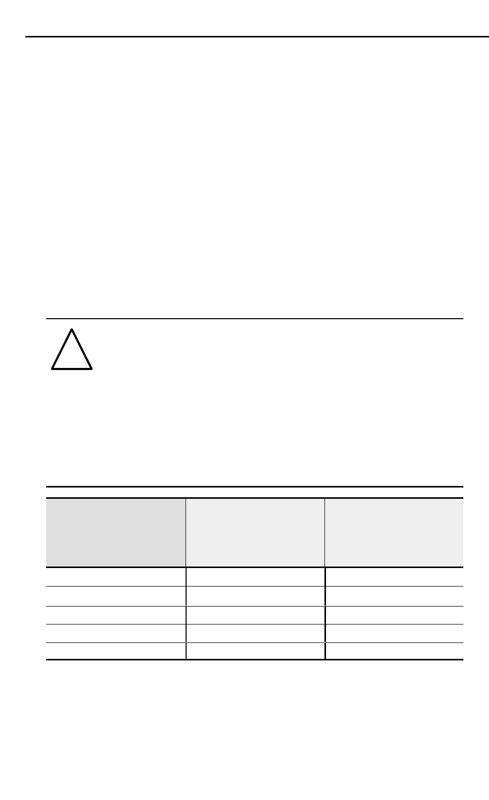
If you are using this
number of standard
(1794) modules:
Then, the maximum
number of 1203
modules that you can
use is:
And, the number of
SCANport connections
provided is:
7 or 8
0
0
5 or 6
1
2
3 or 4
2
4
1 or 2
3
6
0
4
8