Rockwell Automation 1492-CM1771-LD005 Field Conversion Module User Manual
Page 4
There are several key application considerations and system specifications (bottom of drawing) when
using these components (conversion module, cable and input module). Read and understand these
considerations before installation.
WARNING
PN-114277
DIR 10000060088 (Version 01)
Publication 1492-IN035B-EN-E
Printed in U.S.A.
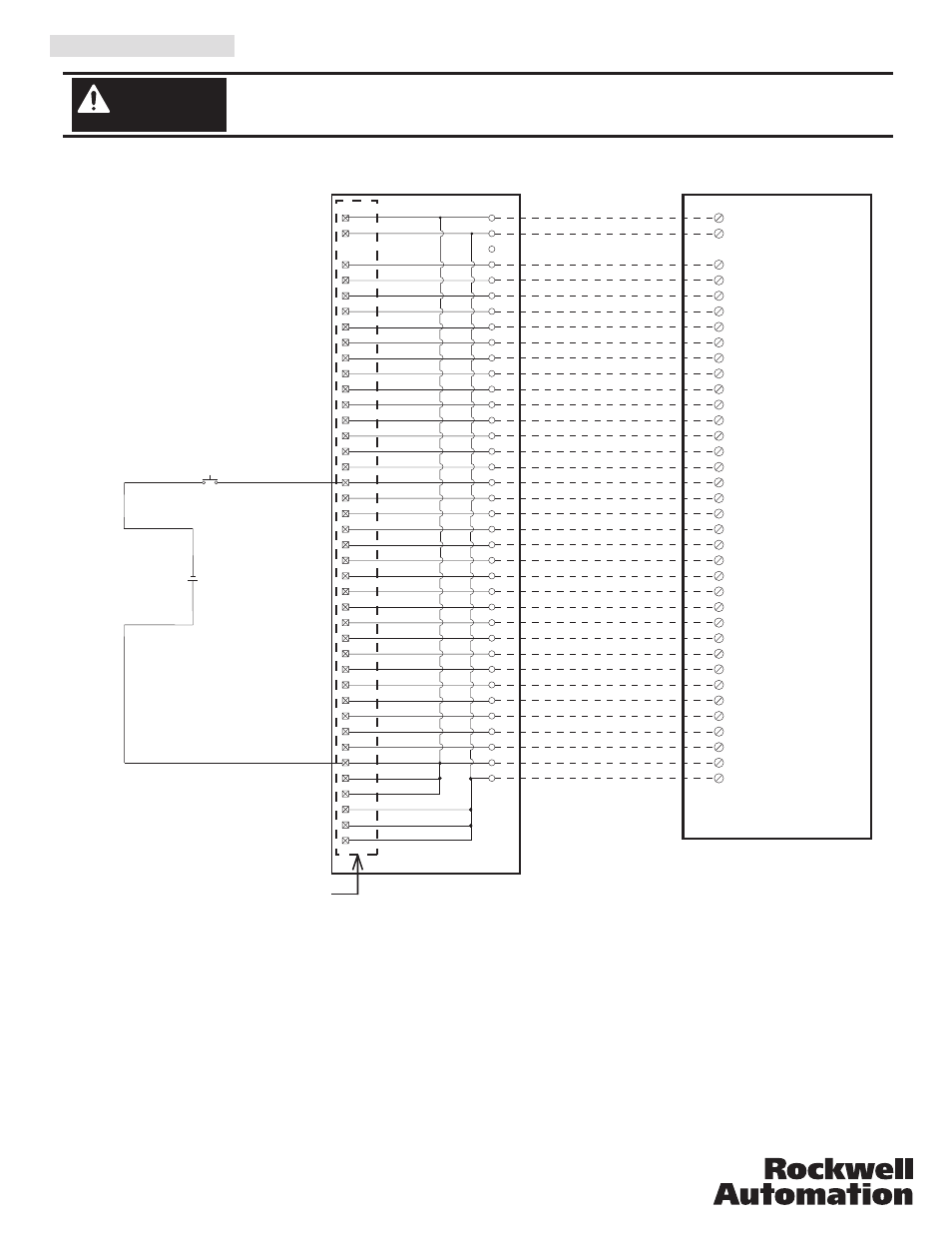
V. Wiring Diagrams
Conversion: 1771-IVN to 1756-IV32
18
DC-0 (+)
IN-0
1
IN-16
19
IN-1
2
IN-17
20
IN-2
3
IN-18
21
IN-3
4
IN-19
22
IN-4
5
IN-20
23
IN-5
6
IN-21
24
IN-6
7
IN-22
25
Black
White
Red
Green
Orange
Blue
White/Black
Red/Black
Green/Black
Orange/Black
Blue/Black
Black/White
Red/White
Green/White
Blue/White
Black/Red
White/Red
Orange/Red
Blue/Red
Red/Green
IN-7
8
1
2
3
4
5
6
4
7
8
5
9
24
10
6
11
25
12
7
13
26
8
9
29
10
30
15
27
16
17
28
18
2
19
20
14
21
22
13
23
24
14
25
33
26
15
27
34
28
16
29
35
30
17
31
36
32
18
33
37
22
35
38
36
37
34
DC-1 (+)
36
IN-23
26
IN-8
9
IN-24
27
IN-9
10
IN-25
28
IN-10
11
IN-26
29
IN-11
12
IN-27
30
IN-12
13
IN-28
31
IN-13
14
IN-29
32
IN-14
15
IN-30
33
Orange/Green
Black/White/Red
White/Black/Red
Red/Black/White
Green/Black/White
Orange/Black/White
Blue/Black/White
Black/Red/Green
White/Red/Green
Red/Black/Green
Green/Black/Orange
Orange/Black/Green
Blue/White/Orange
Black/White/Orange
White/Red/Orange
Orange/White/Blue
IN-15
16
IN-31
34
17
DC-0 (+)
White/Red/Blue
DC-1 (+)
35
Input 01
Input 01
Input 02
Input 02
Input 03
Input 03
Input 04
Input 04
Input 05
Input 05
Input 06
Input 06
Input 07
Input 07
Input 10
Input 11
Input 10
Input 12
Input 13
Input 13
Input 14
Input 14
Input 15
Input 15
Input 16
Input 16
Input 17
Input 17
Input 00
19
39
20
40
1
11
23
10-30V dc (0)
3
Input 00
Input 11
Input 12
31
12
21
32
+
-
10-30V dc (2)
10-30V dc (0)
10-30V dc (1)
10-30V dc (1)
10-30V dc (3)
10-30V dc (2)
10-30V dc (3)
Conversion Module Installation and Application Considerations
The input delay times for the 1771-IVN module versus 1756-IV32 module are as follows:
1771-IVN
1756-IV32
a) Off-to-On Delay
6ms (+/-2ms)
1ms (plus selectable filter)
b) On-to-Off Delay
6ms (+/-2ms)
2ms (plus selectable filter)
The 1771-IVN has 4 groups (allowing 4 seperate power supplies) and the 1756-IV32 has 2 groups.
This module/cable combination ties Groups 0 & 1 from the 1771-IVN to Group 0 on the 1756-IV32 and it ties Groups 2 & 3
from the 1771-IVN to Group 1 on the 1756-IV32.Field wiring modification must be made to accommodate this if multiple
supplies were used. If 4 supplies were used, 2 must be removed.
Refer to your 1771-IVN and 1756-IV32 Installation Manual wiring schematics and diagrams for more details.
[Reference Doc: 41170-934 (Version 02)]
1771-WN Swing Arm
From 1771-IVN
Conversion Module
1492-CM1771-LD005
Cable
1492-CONCAB005Z
1756-IV32