Install relative humidity transmitter, Wire/connect relative humidity transmitter, Wire connections for relative humidity boards – Rockwell Automation 1414-IHZxxxxx_CHZxxxxx Relative Humidity Transmitter User Manual
Page 3
Relative Humidity Transmitter 3
Publication 1414-IN007A-EN-P - October 2005
Install Relative Humidity Transmitter
The Relative Humidity Transmitter can be mounted in a duct or outside the
structure.
Duct - Drill a 5/8“ (or larger) hole in the return air duct. Remove the protective
plastic sleeve from the probe and place it through the hole and secure the
enclosure to the duct with sheetmetal screws. Orientation of the enclosure and
probe has no effect on the operation of the device.
Outside Air – For best results, locate the sensor on the north side of the structure
high under an eave to prevent incorrect readings from direct sunlight and damage
due to the elements. Mount the OSA enclosure with the sensor module facing down
to prevent the accumulation of dirt or water.
Wire/Connect Relative Humidity Transmitter
Anti-static precautions should be followed to prevent damage to the device.
The transmitter should be connected to the controller using twisted pair 18 to 22
AWG wire and requires three wires for voltage and AC operation while only two
wires are required for the factory-default DC 4 to 20 mA loop-powered operation.
Use shielded cable for the highest noise immunity. Do not route signal wires in the
same conduit with power cables as signal degradation may occur. The controller
Analog Input (AI) must be selected to match the transmitter output before power is
applied. The AI type must be a current input with 250 or 500 ohm impedance. Duct
and O.S.A. transmitters have an operating range of –40 to 80 °C (-40 to 170 °F). The
transmitter board should not be mounted where temperatures will exceed these
values. See the connection diagram for more details.
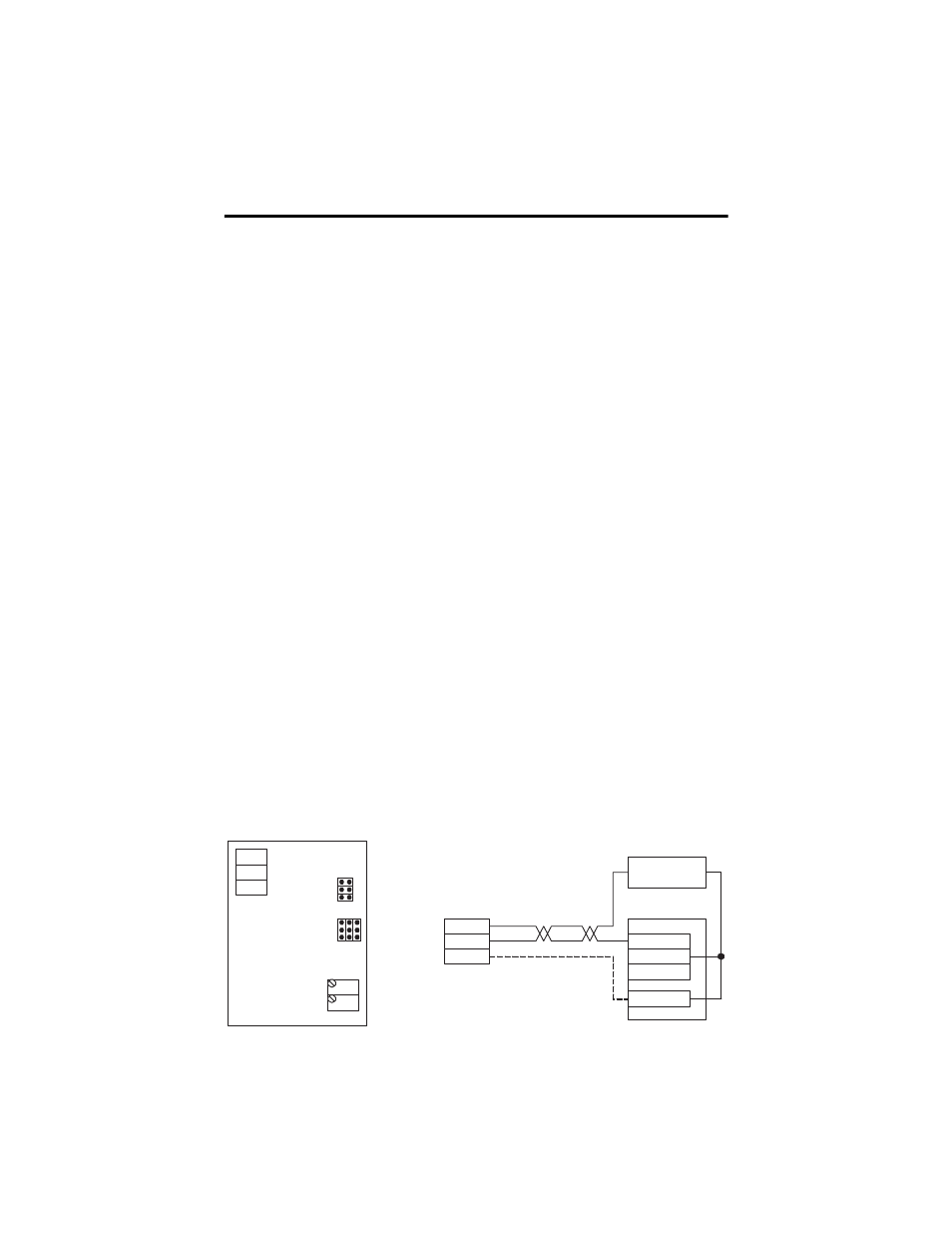
Wire Connections For Relative Humidity Boards
Typical wiring to a controller is shown in the connection diagram.
PWR
COM
OUT
SPAN
ZERO
VOLTAGE
CURRENT
10
5
1
+ 24 VDC -
ANL IN 0 +
ANL IN 0 -
Analog Current/
Voltage Input
ANL COM
Loop power supply
RH Transmitter - Loop powered
or Voltage output
PWR
COM
(SIG) OUT
COM wired only for
voltage outputs