Quick start guide, Digital inputs – tb3, Jumper locations 2 – Rockwell Automation 1336F PLUS II Quick Start Guide User Manual
Page 2: Plus, Frames a1 - a4 frames b - g, J9, j10
1336
PLUS
II
Quick Start Guide
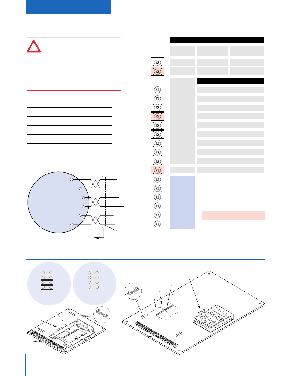
19
20
21
22
23
24
25
26
27
28
29
30
!
A hazard of personal injury from automatic restart exists
with 2-wire control. 2-wire control uses maintained Run
contacts that act as both Run (closed) and Stop (open)
devices. Opening the Stop contact (terminal 20) will stop
the drive. If this contact is reclosed, any fault will be reset.
If a valid Start command is still present, the drive will
restart. Only use 2-wire control for applications outlined in
NFPA79, "Under Voltage Protection."
If a 3-wire device (i.e. HIM) is also used, pressing the HIM
Stop key will also stop the drive. Releasing the Stop key
will clear any faults that are present, but the drive will not
restart without cycling the Start contact.
Input 1
Input 2
Common
Input 3
Input 4
Input 5
Common
Input 6
Input 7
Input 8
Common
Input 9
Encoder B
Encoder NOT A
Encoder NOT B
Encoder A
+12V (200mA max.)
Encoder Common
31
32
33
34
35
36
Included on
L4E through L9E
Only
to TE
Recommended Cable (or equivalent):
Belden 9730 for distances less than 30 meters (98 feet)
Belden 9773 for distances greater than 30 meters (98 feet)
Differential Encoder Output
Connections Shown
Refer to User Manual
for
Single-Ended Connections
1
See
Speed Select Table.
2
If this mode is selected, the status of all inputs can
be read at the [Input Status] parameter. However,
only “Stop/Fault Reset” and “Enable” will have
control function.
3
These inputs must be present (reprogram if
necessary) before drive will start.
4
Bit 0 of [Direction Mask] must = 1 to allow TB3
direction change/bipolar operation.
Speed Select Input State vs. Frequency Source
Speed Select 3
Speed Select 2
Speed Select 1 Frequency Source
Open
Open
Open
[Freq Select 1]
Open
Open
Closed
[Freq Select 2]
Accessed through [Freq Select 2] parameter
[Preset Freq 1]
Open
Closed
Open
[Preset Freq 2]
Open
Closed
Closed
[Preset Freq 3]
Closed
Open
Open
[Preset Freq 4]
Closed
Open
Closed
[Preset Freq 5]
Closed
Closed
Open
[Preset Freq 6]
Closed
Closed
Closed
[Preset Freq 7]
Important: The final speed command may be affected by the type of
modulation selected with [Speed Control], parameter 77.
Refer to [Speed Control] in Chapter 6 of the User Manual for
further information.
Input Mode (Start/Stop Functions Only)
Status
2
(Factory Default)
Status
Stop/Fault Reset
3
2-Wire Control
Single-Source Control
Run Forward
Stop/Fault Reset
3
3-Wire Control
Single-Source Reversing
Start
Stop/Fault Reset
3
Common
Rev/For
4
(Programmable)
Factory Default Inputs
Jog (Programmable)
Auxiliary
3
(Programmable)
Common
Speed Select 3
1
(Programmable)
Speed Select 2
1
(Programmable)
Speed Select 1
1
(Programmable)
Common
Enable
3
(Not Programmable)
Enable
3
Status Only
Default Mode
shown at right
is not active
when
[Input Mode]
is set to "Status"
Digital Inputs – TB3
Frames A1 - A4
Frames B - G
JOG
ES
C
SE
L
Connector J9
Connector J10
J8, J11, J13
TB2-4
Common
TB2-3
Input 1
TB2-2
Input 0
TB2-1
Pot Ref. (5V)
TB2-9
Common
TB2-8
Output 1
TB2-7
Output 0
TB2-6
Input 2
Text Does Not Appear on Board
(for explanation purposes only)
Remaining Pins
Not Shown
Text Does Not Appear on Board
(for explanation purposes only)
Remaining Pins
Not Shown
J9, J10
J9, J10
Slot B
Slot A
Slot B
Slot A
TB2
TB2
J8, J11, J13
J2
J2
ANALOG I/O
SLO
T B
8
6
4
2
7
5
3
1
J10
ANALOG I/O
SLO
T A
8
6
7
5
3
1
J9
ANALOG I/O
SLO
T B
8
6
4
2
7
5
3
1
J10
ANALOG I/O
SLO
T A
8
6
7
5
3
1
J9
Jumper Locations
2