Rockwell Automation 1102C-PKxx 400A / 600A Vacuum Contactor AC Coil Replacement User Manual
Page 2
42052-091
G. Ushakow
N/A
N/A
N/A
42052
1006490
1
INSTRUCTION SHEET
BULLETIN 1102C 400A/600A VACUUM CONTACTOR
AC COIL REPLACEMENT
2-19-04
Mark Jutz
2-19-04
D. Josef
2-19-04
2
4
REVISION
AUTHORIZATION
DIMENSIONS APPLY BEFORE
SURFACE TREATMENT
H
A
B
C
D
E
F
G
(DIMENSIONS IN INCHES)
TOLERANCES UNLESS
OTHERWISE SPECIFIED
REFERENCE
SHEET
OF
DWG.
B
DR.
CHKD.
APPD.
DATE
DATE
DATE
±
±
±
ANGLES:
.XXX:
.XX:
THIS DRAWING IS THE PROPERTY OF
THE ALLEN-BRADLEY CO. INC.
AND MAY NOT BE COPIED, USED OR
DISCLOSED FOR ANY PURPOSE EXCEPT
AS AUTHORIZED IN WRITING BY
THE ALLEN-BRADLEY CO. INC.
LOCATION : MILWAUKEE,
WISCONSIN
U.S.A.
SIZE
1
2
3
4
5
6
7
8
E - DOC
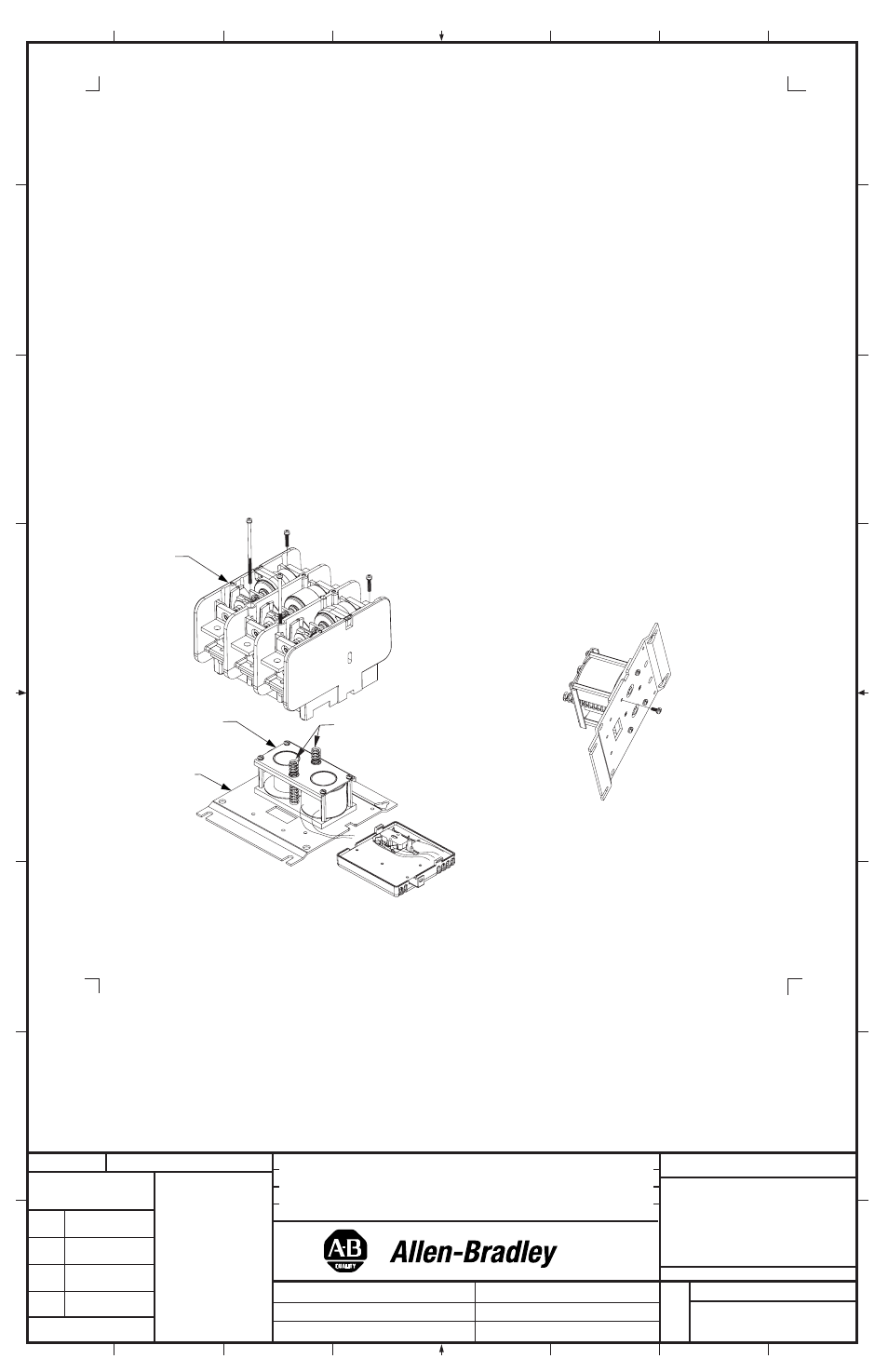
Coil Replacement (Cont'd)
6. While supporting the Main Housing, remove the Main Housing from the Baseplate by removing the (4) screws which
hold the housing to the Baseplate. A long philips-head screwdriver (6 inch or longer) is needed as the four screws are
in deep wells (holes) in the Main Housing. Remove the shorter screws first. Separate the main housing assembly
from the Baseplate and set it aside
(Figure 3).
7. Remove the Return Springs and set them aside (Figure 3). Turn the Base Assembly over and remove the (4)
screws that secure the Coil Assembly to the Baseplate
(Figure 4).
8. Install new Coil Assembly in position using (4) screws (torque to 30 - 45 lb-inches). Replace the Return Springs by
placing them over the spring support pins located within the coil magnet core assembly making sure the return springs
are properly seated and not interfering with any of the control wiring
(Figure 3).
9. Carefully replace the Main Housing assembly loosely, making sure it is orientated correctly. Ensure that no wires
are pinched between housing and baseplate. Carefully locate the magnetic armature poles (the poles sticking down
from the upper housing assembly) into the coil magnet core assembly.
Note: This is a blind operation with careful
side to side motion. Pay close attention to alignment of the locating bosses located at the bottom of the main housing
assembly. To reattach the Main Housing assembly insert the main housing locating bosses into the two mounting
plate holes while compressing the return springs with the Main Housing. Start the four Main Housing screws into the
mounting plate. Tighten the mounting screws equally in a diagonal pattern approximately two turns at a time until
torqued to 28 lb-inches in the same diagonal pattern.
Figure 3
Figure 4
Main
Housing
Coil
Assembly
Baseplate
Return
Springs
(2)