Install the common mode choke – Rockwell Automation 1321-M055 Common Mode Choke User Manual
Page 2
1321-M055 Common Mode Choke
Publication 1321-IN002A-EN-P - October 2014
PN-282180
Copyright © 2014 Rockwell Automation, Inc. All rights reserved. Printed in the U.S.A.
Rockwell Automation maintains current product environmental information on its website at
Allen-Bradley, Rockwell Software, and Rockwell Automation are trademarks of Rockwell Automation, Inc.
Trademarks not belonging to Rockwell Automation are property of their respective companies.
U.S. Allen-Bradley Drives Technical Support - Tel: (1) 262.512.8176, Fax: (1) 262.512.2222, E-mail:
.
Rockwell Otomasyon Ticaret A.Ş., Kar Plaza İş Merkezi E Blok Kat:6 34752 İçerenköy, İstanbul, Tel: +90 (216) 5698400
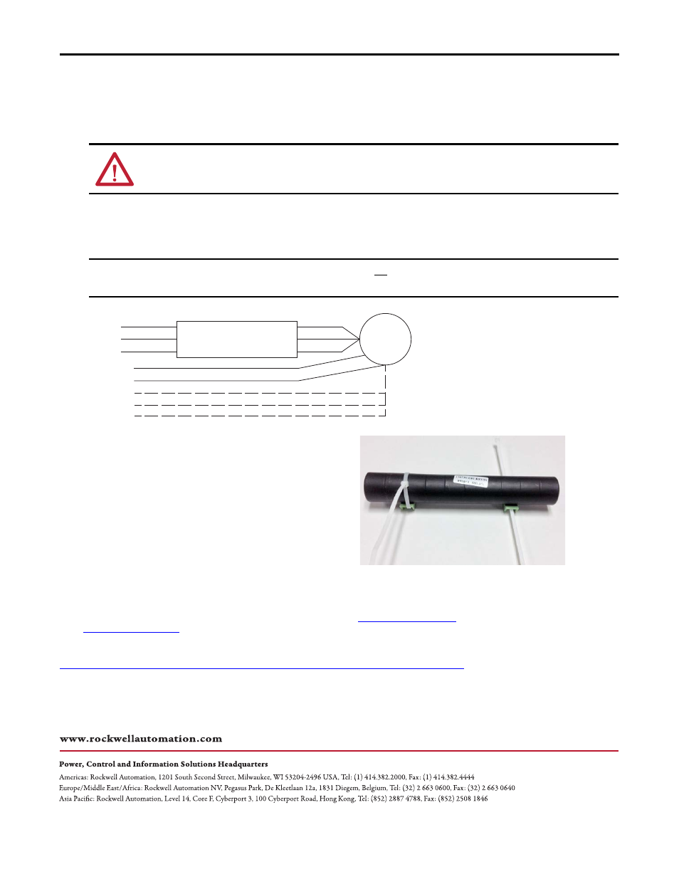
Install the Common Mode Choke
Follow theses steps to install the common mode choke.
1. Remove all power from the system.
2. If used, secure the mounting brackets (provided in the kit) to a panel using customer-supplies screws.
3. Remove the motor leads from the drive terminals U, V, and W.
4. Feed the motor leads through the common mode choke.
5. Secure the choke to the mounting brackets or
cabinet sheet metal surface by using tie wraps.
Note: If the choke is mounted in a vertical
orientation, without the mounting brackets,
additional tie wraps may be required to secure the
choke so it does not slip off the mounting surface.
6. Reconnect the motor leads.
ATTENTION: Electric shock can cause injury or death. Remove all power before working with this product. Verify that the
voltage on the drive bus capacitors has discharged. The voltage must be zero.
IMPORTANT
Only route the three motor leads through the choke. Do not route the motor shield, PE ground, and the brake leads (if
present) through the choke.
U
V
W
M
PE GND
Motor Shield
Brake 1
Brake 2
Brake Shield
Common Mode Choke