Iv. conversion module wiring diagram, Module a module b – Rockwell Automation 1492-CM800-LD012 Field Wire Conv. Module for Modicon B838-032 to Two 1756-OB16E User Manual
Page 2
(2)
10000021903
(Version 00)
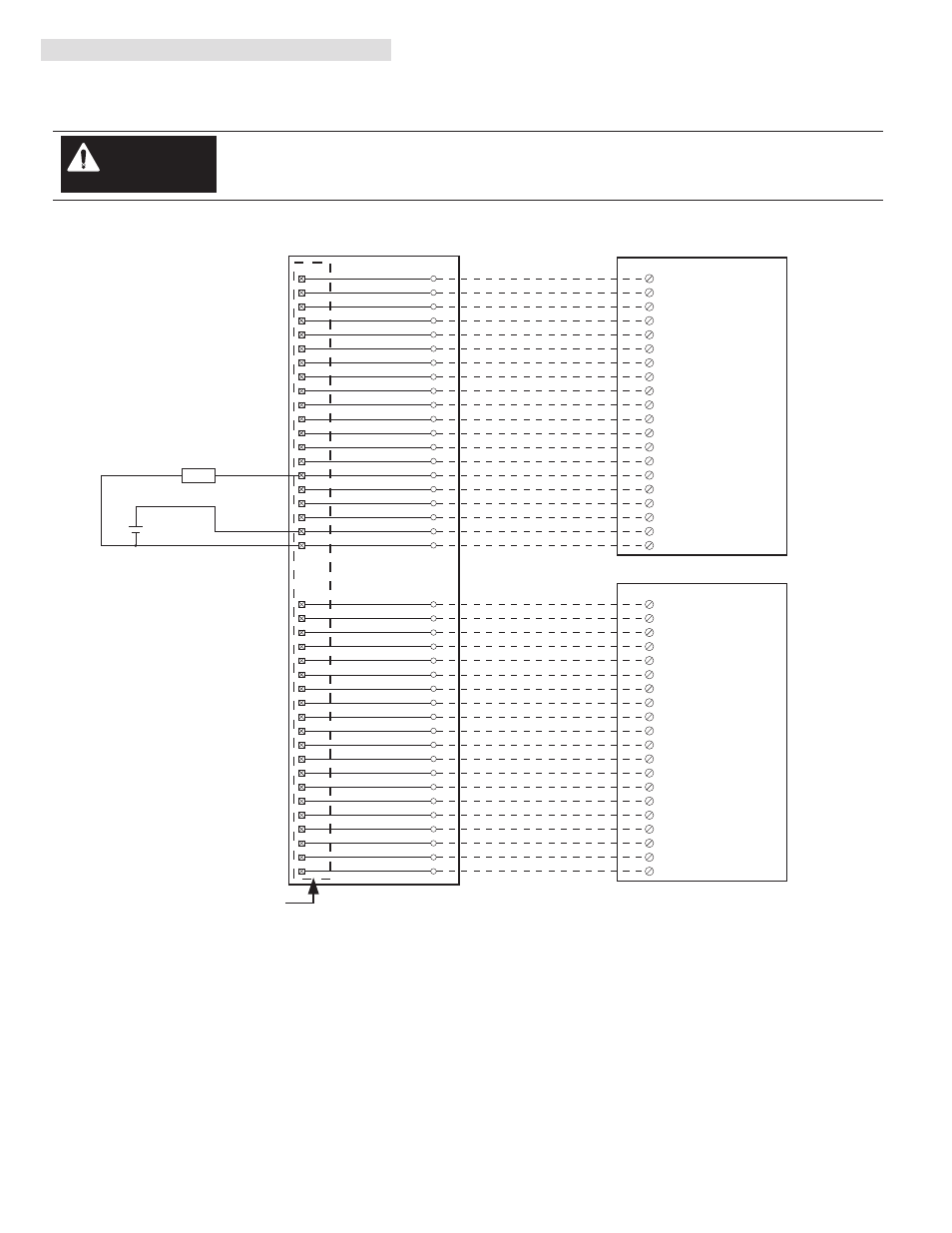
IV. Conversion Module Wiring Diagram
The following diagram shows the connections from the existing B838-032 swing-arm, through the conversion module, two 1492
cables and to the two 1756-OB16E output modules. The diagram can be used as an aid in possible system troubleshooting.
1756-OB16E
1756-OB16E
1492-CABLE003X
1492-CABLE003X
1492-CM800-LD012
Conversion: B838-032 to 1756-OB16E Qty 2 with 1492-CM800-LD012
B838-032 Swing Arm
Conversion Module Installation and Application Considerations
This configuration uses two (2) 1756-OB16E output modules to replace a single B838-032 output module. This may require
the use of a larger 1756 I/O Chassis. Ensure there is sufficient panel space to allow for this possibility.
The B838-032 module output current limits versus 1756-OB16E limits are as follows:
B838-032
1756-OB16E w/ 1492-CABLE003X
a) Current/Point
0.5A
1A
b) Current/Group
----
2A
c) Current/Module
16A (32 pts)
4A (16 pts)
d) Surge Current/Pt
2.5A for 0.5ms
2A for 10ms
The B838-032 module provided a single mechanical fuse per group. The 1756-OB16E is electronically fused per group.
Refer to the 1756-OB16E Installation Manual for electronic fusing details.
The 1492-CABLE003X current is limited to 2A per pin.
Refer to your B838-032 and 1756-OB16E Installation Manual wiring schematics and diagrams for more details. Ensure
1756 output module ratings are not exceeded.
[Reference Doc: 41170-762 (Version 03)]
1
2
3
4
1
5
21
6
2
7
22
8
3
9
23
10
4
11
24
12
7
13
27
8
15
28
16
9
17
29
18
10
19
30
20
14
11
31
12
32
13
33
14
34
17
37
18
38
19
39
20
40
26
16
Output 1
Output 17
Output 2
Output 18
Output 3
Output 19
Output 4
Output 20
Output 5
Output 21
Output 6
Output 22
Output 7
Output 23
Output 8
Output 24
Output 9
Output 25
Output 10
Output 26
Output 11
Output 27
Output 12
Output 28
Output 13
Output 29
Output 14
Output 30
Output 15
Output 31
Output 16
Output 32
36
5
6
Group 1(-)
+
-
LOAD
25
15
35
Group 3(-)
Group 2(-)
Group 4(-)
Group 1(+)
Group 3(+)
Group 2(+)
Group 4(+)
10
DC-0+
OUT-0
1
OUT-1
2
OUT-2
3
OUT-3
4
OUT-4
5
OUT-5
6
OUT-6
7
OUT-7
8
OUT-8
11
OUT-9
12
OUT-10
13
OUT-11
14
OUT-12
15
OUT-13
16
OUT-14
17
OUT-15
18
Black
White
Red
Green
Orange
Blue
White/Black
Red/Black
Green/Black
Orange/Black
Blue/Black
Black/White
Red/White
Green/White
Blue/White
Black/Red
White/Red
Orange/Red
Blue/Red
Red/Green
DC-1+
20
9
RTN OUT-0
19
RTN OUT-1
1
2
3
4
5
6
7
8
9
10
11
12
13
15
16
17
18
19
20
14
10
DC-0+
OUT-0
1
OUT-1
2
OUT-2
3
OUT-3
4
OUT-4
5
OUT-5
6
OUT-6
7
OUT-7
8
OUT-8
11
OUT-9
12
OUT-10
13
OUT-11
14
OUT-12
15
OUT-13
16
OUT-14
17
OUT-15
18
Black
White
Red
Green
Orange
Blue
White/Black
Red/Black
Green/Black
Orange/Black
Blue/Black
Black/White
Red/White
Green/White
Blue/White
Black/Red
White/Red
Orange/Red
Blue/Red
Red/Green
DC-1+
20
9
RTN OUT-0
19
RTN OUT-1
MODULE
A
MODULE B
P1
P2
There are several key application considerations and system specifications (bottom of drawing) when
using these components (conversion module, cable and output module). Read and understand these
considerations before installation.
WARNING