Field calibration – Rockwell Automation 1414-CTIxxxxx_ITIxxxxx Immersion Temperature Transmitter User Manual
Page 4
4 Immersion Temperature Transmitter
Publication 1414-IN008A-EN-P - October 2005
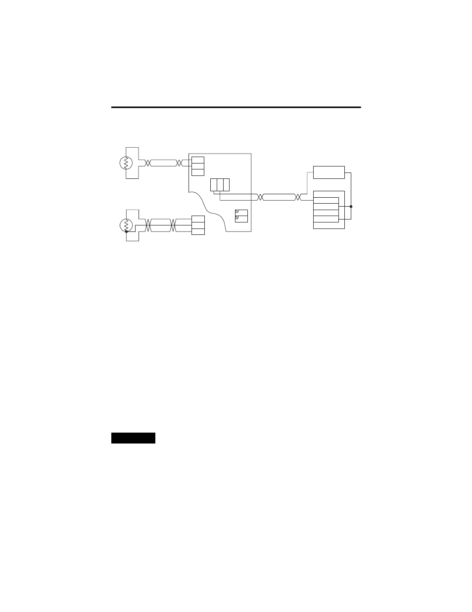
All two wire sensors are polarity insensitive. Three-wire RTD sensors are used in
high temperature range applications (maximum temperature > 212°F). If desired. a
three-wire sensor may be connected as two-wire by connecting together the
EXCitation and SENse lines. If used, wire splices should be made using either
buttsplices or soldering. The use of wire nuts is not recommended.
For 4 to 20 mA loop signal, only the PWR and OUT terminals are used.
High temperature probes have three wires; two wires of one color (usually black)
and the third wire a different color (usually white).
Field Calibration
The unit can be calibrated in the field by using precision resistor values equal to the
zero and span of the transmitter temperature range.
1. Disconnect the sensor from the transmitter and connect the resistor that
represents the zero value to the EXC and NEG terminals.
2. Adjust the ZERO pot until the desired output is achieved.
3. Connect the resistor that represents the span value to the EXC and NEG
terminals.
4. Adjust the SPAN pot until the desired output is achieved.
TIP
If the unit uses a three-wire sensor, a jumper must be placed
between EXC and SEN.
NEG
EXC
SEN
PW
R
CO
M
OU
T
SPAN
ZERO
+ 24 VDC -
ANL IN 0 +
ANL IN 0 -
Analog Current Input
ANL COM
Loop power supply
2-wire RTD
Sensor
Temperature Transmitter
NEG
EXC
SEN
3-wire RTD
Sensor
RED
GRN
BLK