Iv. conversion module wiring diagram (continued) – Rockwell Automation 1492-CM800-LD007 Field Wire Conv. Module for Modicon B821-108 to 1756-IC16 User Manual
Page 3
(3)
10000021878
(Version 00)
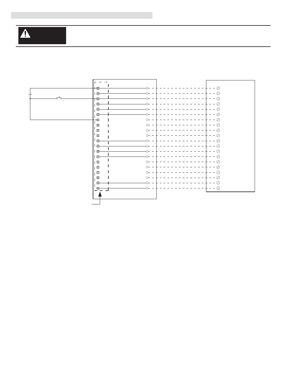
IV. Conversion Module Wiring Diagram (Continued)
Conversion: B821-108 to 1756-IC16 with 1492-CM800-LD007
1756-IC16
1492-CABLE003X
1492-CM800-LD007
B821-108 Swing Arm
Conversion Module Installation and Application Considerations
The voltage range of the B821-108 module is 10-60V DC and the 1756-IC16 is 30-60V DC. If the input source voltage is
less than 30V DC, use the 1756-IB16.
The input delay times for the B821-108 module versus 1756-IC16 module are as follows:
B821-108
1756-IC16
a) Off-to-On Delay
2.5ms (min),11ms (max)
1ms (plus selectable filter)
b) On-to-Off Delay
2.5ms (min),11ms (max)
2ms (plus selectable filter)
The B821-108 has 4 groups (allowing 4 separate power supplies) and the 1756-IC16 has 2 groups. This module/cable
combination ties Groups 1 & 2 from the B821-108 to Group 0 on the 1756-IC16 and it ties Groups 3 & 4 from the B821-108 to
Group 1 on the 1756-IC16. Field wiring modification must be made to accommodate this if multiple supplies were used. If 4
supplies were used, 2 must be removed. NOTE: To allow for multiple supplies in this conversion, the Inputs do not map directly
to the equivalent input. For example: Input 5 on the B821-108 maps to Input 8 on the 1756-IC16, the user needs to account for
this in the controller program.
Refer to your B821-108 and 1756-IC16 Installation Manual wiring schematics and diagrams for more details.
[Reference Doc: 41170-769 (Version 03)]
3
1
1
19
2
3
7
4
8
5
11
6
12
7
17
8
18
9
10
11
4
12
10
13
14
20
15
5
16
6
17
15
16
18
20
14
2
+
-
Input 5
Input 7
Input 6
Input 8
Input 1
Input 3
Input 2
Input 4
Group 1 Common
Not Used
Not Used
9
Group 2 Common
13
Group 3 Common
19
Group 4 Common
Group 1 Supply Volt
Group 2 Supply Volt
Group 3 Supply Volt
Group 4 Supply Volt
Not Used
Not Used
10
GND-0
IN-0
1
IN-1
2
IN-2
3
IN-3
4
IN-4
5
IN-5
6
IN-6
7
IN-7
8
IN-8
11
IN-9
12
IN-10
13
IN-11
14
IN-12
15
IN-13
16
IN-14
17
IN-15
18
Black
White
Red
Green
Orange
Blue
White/Black
Red/Black
Green/Black
Orange/Black
Blue/Black
Black/White
Red/White
Green/White
Blue/White
Black/Red
White/Red
Orange/Red
Blue/Red
Red/Green
GND-1
20
9
GND-0
19
GND-1
There are several key application considerations and system specifications (bottom of drawing) when
using these components (conversion module, cable and output module). Read and understand these
considerations before installation.
WARNING