Rockwell Automation 1102C-VB2 200A Vacuum Contactor Vacuum Interrupter Phase Assembly Replacement User Manual
Page 2
42052-093
G. Ushakow
N/A
N/A
N/A
42052
1006490
1
INSTRUCTION SHEET
BULLETIN 1102C 200A VACUUM CONTACTOR
VACUUM INTERRUPTER PHASE ASSEMBLY
REPLACEMENT
2-24-04
Mark Jutz
2-24-04
D. Josef
2-24-04
2
2
REVISION
AUTHORIZATION
DIMENSIONS APPLY BEFORE
SURFACE TREATMENT
H
A
B
C
D
E
F
G
(DIMENSIONS IN INCHES)
TOLERANCES UNLESS
OTHERWISE SPECIFIED
REFERENCE
SHEET
OF
DWG.
B
DR.
CHKD.
APPD.
DATE
DATE
DATE
±
±
±
ANGLES:
.XXX:
.XX:
THIS DRAWING IS THE PROPERTY OF
THE ALLEN-BRADLEY CO. INC.
AND MAY NOT BE COPIED, USED OR
DISCLOSED FOR ANY PURPOSE EXCEPT
AS AUTHORIZED IN WRITING BY
THE ALLEN-BRADLEY CO. INC.
LOCATION : MILWAUKEE,
WISCONSIN
U.S.A.
SIZE
1
2
3
4
5
6
7
8
E - DOC
Vacuum Interrupter Phase Assembly
Replacement (Cont'd)
6. Locate the replacement Interrupter Phase Assembly that needs to be replaced. It is recommended that all three
interrupters be replaced at the same time.
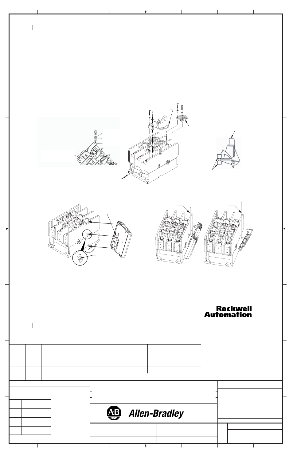
7. Remove the hardware that secures the shunt to the terminal (Figure 3).
8. First remove the hardware securing the Cam Cover, then remove the hardware securing the Interrupter Phase
Assembly. Note the position of the shunt prior to removing the Interrupter Phase Assembly. Carefully remove the
Interrupter Phase Assembly
(Figure 4).
9. Place the new Interrupter Phase Assembly into the upper housing. Ensure that the Cams are properly seated around
the Contact Operator. Thread the Shunt through the housing and Contact Operator, following the Shunt path
(Figure 5).
Replace the hardware securing the Interrupter Phase Assembly
(Figure 4). Torque screws to 80 lb-inches.
10. Attach the Shunt to the Load Terminal by placing the Shunt against the Terminal with the flat washer and lock washer
between the Shunt and the head of the bolt
(Figure 3). Torque to 60 lb-inches).
11. Replace the Cam Cover and hardware (torque to 12 lb-inches).
12. Reinstall the Control-Pak (Figures 6A & 6B). First, insert the lower tab into the recess on the side of the contactor
base. With proper installation, the Actuator will fit into the hole in the slot in the side of the contactor housing. Using a thin
rod or flat blade, lift the Actuator up as necessary to insert it into the slot mentioned.
13. Reinstall the cover and secure it with the original mounting hardware. NOTE: Cover must fit under metal bracket on
Control-Pak. Tighten the two screws to 12 lb-inches (Figure 1).
14. Reattach the coil wire leads and any auxiliary control wires to the Control-Pak (tighten to 7 lb-inches).
15. Reinstall the contactor.
16. Reconnect the line and load conductors and tighten the main terminal hardware and bolts to 125 - 145 lb-inches.
Replacement (Cont'd)
42052-089-01 (1)
Printed in U.S.A.
10. Re-install the Control-Pak (FIGURES 5A & 5B). First, rotate the Retainer upwards. Next, insert the lower tab
into the recess on the side of the contactor base. With proper installation, the Actuator will fit into the hole in the
slot in the side of the contactor housing. Using a thin rod or flat blade, lift the Actuator up as necessary to insert
it into the slot mentioned. Rotate the Retainer to its original position, which will slide over the upper tab on the
Control-Pak.
11. Confirm position of (2) retainers (adjust if necessary) (See Figure 1).
12. Reinstall the cover and secure it with the original mounting hardware. NOTE: cover must fit under metal
bracket on Control-Pak. Tighten the four screws in a diagonal pattern to 12 lb-in.
(Figure 1).
13. Reattach the coil wire leads and any auxiliary control wires to the Control-Pak (tighten to 7 lb-in).
14. Reinstall the contactor. Torque mounting screws to 50 - 75 lb-in.
15. Reconnect the line and load conductors and tighten the main terminal hardware and bolts to 15- 20 lb-ft.
Actuator
must fit into slot
shown
Figure 5A
Figure 5B
Control-Pak
Actuator
Thin rod or flat blade
Control-Pak
Actuator
Actuator
must fit into slot
shown
Figure 6A
Figure 6B
Thin rod or flat blade
Thin rod or flat blade
42052-093-01 (1)
Printed in U.S.A.
Figure 3
Figure 4
Figure 5
Cam
Cover
Interrupter
Phase Assembly
Shunt
Shunt Path
Cam
Orientation
Contact
Operator
Bottom View of Upper
Housing Assembly
Lockwasher
Washer
Shunt
PART
NO.
MATERIAL
CHG.
LTR.
SIZE
FLAT
FOLD
-01
1
TWO SIDES PRINTED
8-1/2" W x 11" H
BODY STOCK WHITE
BODY INK BLACK
4-1/2" W x 5-1/2" H