Rockwell Automation 1606-XLS960EE DC Power Supply User Manual
Page 4
1606-XLS960EE: 1-Phase Power Supply Instruction Manual
1606-XLS960EE: Bedienungsanleitung für 1-Phasen Stromversorgung
EMC Electromagnetic Compatibility
This power supply is suitable for applications in industrial environment as well as in residential,
commercial and light industry environment without any restrictions. This device complies with
FCC Part 15 rules. The CE mark is in conformance with EMC guidelines 89/336/EC, 93/68/EC
and 2004/108/EC as well as the low-voltage directives (LVD) 73/23/EC, 93/68/EC, 2006/95/EC.
EMC Immunity: EN 61000-6-1, EN 61000-6-2
EMC Emission EN 61000-6-3, EN 61000-6-4, FCC Part 15 Class B
EMV Elektromagnetische Verträglichkeit
Diese Stromversorgung erfüllt die Anforderungen für Anwendungen in industrieller Umgebung
und für den Wohn-, Geschäfts- und Gewerbebereich ohne Einschränkungen. Das Gerät erfüllt
auch die Anforderungen der FCC Teil 15. Das CE Zeichen ist angebracht und erklärt die Erfüllung
der EMV Richtlinien 89/336/EG, 93/68/EG und 2004/108/EG wie auch der
Niederspannungsrichtlinien 73/23/EG, 93/68/EG, 2006/95/EG.
Störfestigkeit: EN 61000-6-1, EN 61000-6-2
Störaussendung: EN 61000-6-3, EN 61000-6-4, FCC Part 15 Klasse B
Indicators, LEDs
Overload LED
DC-OK LED
DC-OK Contact
Normal mode
OFF
ON
Closed
During BonusPower
®
OFF
ON
Closed
Overload (Hiccup mode)
flashing
OFF
Open
Output short circuit
flashing
OFF
Open
Temperature Shut-down
flashing
OFF
Open
Active Shut-down input
flashing
OFF
Open
No input power
OFF
OFF
Open
Anzeigelampen
Overload LED
DC-OK LED
DC-OK Contact
Normalbetrieb AUS
EIN
geschlossen
Während BonusPower
®
AUS
EIN
geschlossen
Überlast (Hiccup- Modus)
blinken
AUS
offen
Ausgangskurzschluss blinken AUS
offen
Temperaturabschaltung blinken
AUS
offen
Aktiver „shut-down“ Eingang
blinken
AUS
offen
Keine Eingangsspannung
AUS
AUS
offen
DC-OK Relay Contact
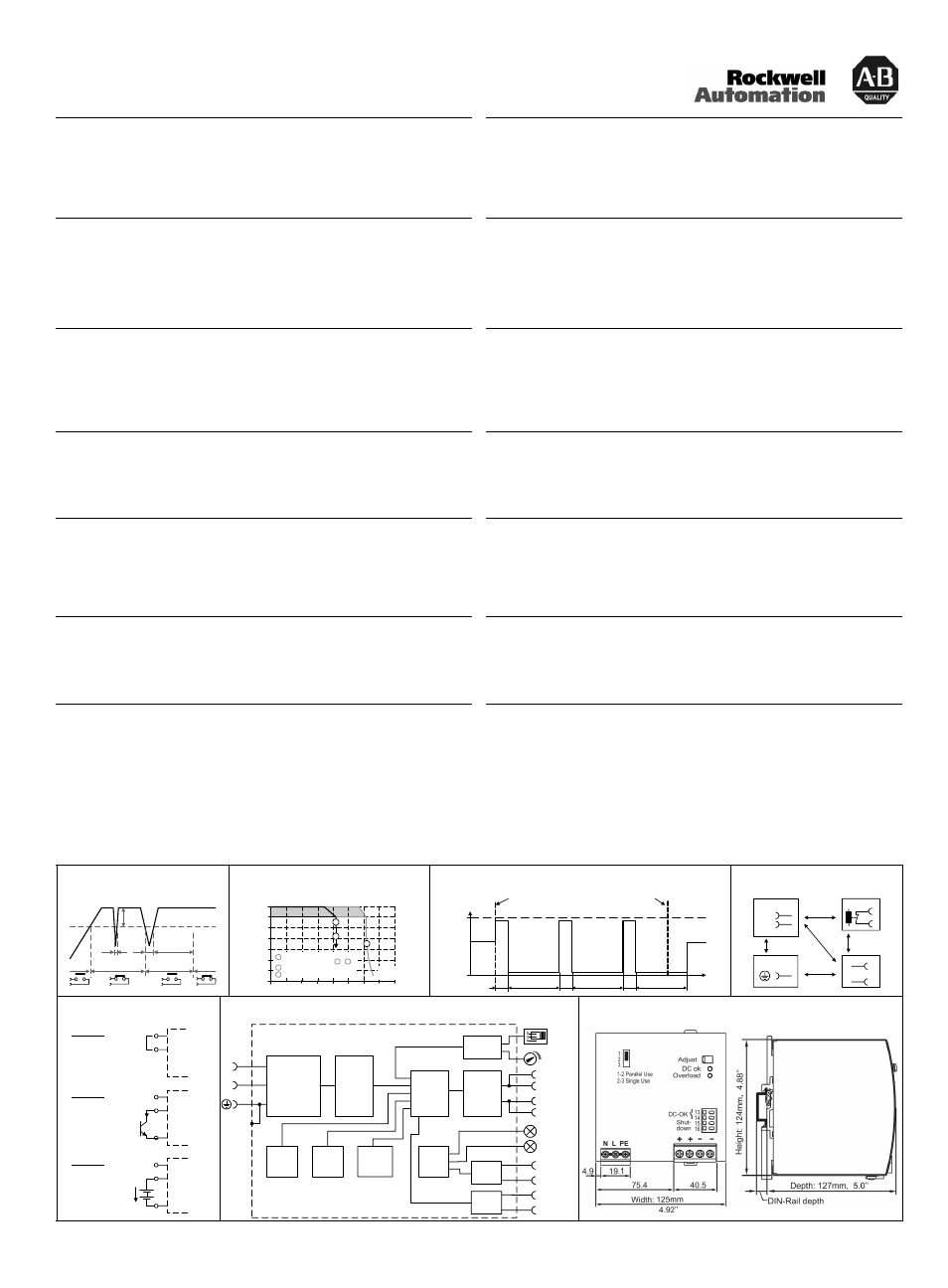
(see Fig. 1)
This feature monitors the output voltage, which is produced by the power supply, and is
independent of a return voltage from a unit which is connected in parallel.
Contact closes when the output voltage reaches the adjusted value after turn-on of the power
supply or when the output voltage reaches 90% after a dip in the output.
Contact opens when the output voltage dips more than 10%. Short dips will be extended to a
length of 250ms. Dips shorter than 1ms will be ignored.
Contact ratings: max.: 60Vdc 0.3A, 30Vdc 1A, 30Vac 0.5A, resistive load, min. current 1mA
DC-OK Relais Kontakt
(siehe Bild 1)
Diese Funktion überwacht die vom Gerät erzeugte Ausgangsspannung und lässt sich von einer
rückwärts eingespeisten Spannung nicht beeinflussen (z.B.: bei Parallelschaltung)
Kontakt schließt sobald nach dem Einschalten der Ausgang den eingestellten Wert erreicht oder
wenn nach Einbruch des Ausgangs die Spannung wieder >90% des eingestellten Wertes wird.
Kontakt öffnet sobald der Ausgang um mehr als 10% einbricht. Kurze Einbrüche werden auf
250ms verlängert. Einbrüche kürzer 1ms werden ignoriert.
Kontakt Belastbarkeit: max.: 60Vdc 0.3A, 30Vdc 1A, 30Vac 0.5A, (R-Last), min. Strom 1mA
Shut-down Input
(see Fig. 5)
This feature allows to switch-off the power supply with a signal switch or an external voltage. The
shut-down function has no safety feature included. The shut-down occurs immediately while the
turn-on is delayed by 350ms. In a shut-down condition, the output voltage is <2V and the output
power is <0.5W. The voltage between different –pole output terminals must be below 1V when
units are connected in parallel. In a series operation of multiple power supplies only wiring option
“A” with individual signal switches is allowed.
„Shut-down“ Eingang
(siehe Bild 5)
Abschaltung des Gerätes durch einen Signalschalter oder eine Fremdspannung. Die Abschaltung
beinhaltet keine Sicherheitsfunktionen. Die Abschaltung erfolgt unverzögert, das
Wiedereinschalten mit einer Verzögerung von ca. 350ms. Im abgeschaltetem Zustand ist die
Ausgangsspannung <2V und die Ausgangsleistung <0,5W. Bei parallel geschalteten Geräten
darauf achten, dass der Spannungsunterschied zwischen den Minus Power Klemmen kleiner 1V
ist. Bei Serienschaltung Schaltungsoption „A“ mit getrennten Schaltern verwenden.
Output- and Overload Characteristic
(see Fig. 2 and 3)
The unit is designed to support loads with a higher short-term power requirement without damage.
The unit can deliver up to 1440W (BonusPower
®
) output power for typ. 4s before it reduces the
output power automatically to 960W. If the power requirement is continuously higher than 960W
and the voltage falls below approx. 85% of its nominal value (due to the current regulating mode
at overload), the unit shuts off and makes periodical restart attempts (hiccup mode). In such
cases, the unit will be off for 17s followed by an on cycle of 2s. This cycle is repeated as long as
the overload exists.
Ausgangs- und Überlastverhalten
(siehe Bild 2 und 3)
Die Stromversorgung kann kurzzeitig hohe Spitzenleistungen liefern und nimmt dabei keinen
Schaden. Für typ. 4s stehen bis zu 1440W Ausgangsleistung (BonusPower
®
) zur Verfügung,
bevor automatisch auf 960W zurückgeregelt wird. Wenn der Leistungsbedarf dauerhaft >960W ist
und durch die Stromregelkennline die Ausgangsspannung unter ca. 85% fällt, schaltet die
Stromversorgung ab und macht periodische Startversuche (Hiccup-mode). In solchen Fällen
schaltet das Gerät für 17s aus und macht danach einen neuen Startversuch mit einer Dauer von
2s. Der Vorgang wiederholt sich solange bis die Überlast entfernt ist.
Parallel-Use to Increase the Output Power
The output voltage shall be adjusted to the same value (±100mV) in “Single Use” at the same
load condition on all units, or shall be left with the factory settings. Afterwards, the jumper on the
front of the unit shall be moved from “Single Use” to “Parallel Use”, in order to achieve a load
sharing. The “Parallel Use” mode regulates the output voltage in such a manner that the voltage
at no load is approx. 5% higher than at nominal load. If no jumper is plugged in, the unit is in
“Single Use”. Factory setting is “Single Use”.
Parallelbetrieb zur Leistungserhöhung
Hierzu alle Geräte bei gleicher Belastung in „Single Use“ auf ±100mV genau einstellen oder die
Ausgangsspannung auf Werkseinstellung belassen. Danach die Steckbrücke an der Front des
Gerätes von „Single Use“ auf „Parallel Use“ umstecken, um eine Aufteilung des Laststromes
zwischen den Geräten zu erreichen. In „Parallel Use“ ist die Ausgangsspannung so geregelt, dass
diese im Leerlauf um etwa 5% höher ist als bei Nennlast. Ein nicht eingesteckter Jumper bedeutet
„Single Use“. Werkseinstellung ist „Single Use“.
Dielectric Strength
(see Fig. 4)
The output voltage is floating and separated from the input according to SELV (IEC/EN 60950-1)
and PELV (EN 60204-1, EN 50178; IEC 62103, IEC 60364-4-41) requirements. Type and factory
tests are conducted by the manufacturer. Field tests may be conducted in the field using the
appropriate test equipment which applies the voltage with a slow ramp (2s up and 2s down).
Connect all phase-terminals together as well as all output poles before the test is conducted.
When testing, set the cut-off current settings to the value in the table below.
A B
C
D
Type Test (60s)
2500Vac
3000Vac
500Vac
500Vac
Factory Test (5s)
2500Vac
2500Vac
500Vac
500Vac
Field Test (5s)
2000Vac
2000Vac
500Vac
500Vac
Cut-off current setting
>20mA
>20mA
>80mA
>20mA
Isolationsfestigkeit
(siehe Bild 4)
Die Ausgangsspannung hat keinen Bezug zur Erde oder Schutzleiter und ist zum Eingang nach
den SELV (IEC/EN 60950-1) und PELV (EN 60204-1, EN 50178, IEC 62103, IEC 60364-4-41)
Standards getrennt. Typ- und Stückprüfungen werden beim Hersteller durchgeführt. Wieder-
holungsprüfungen dürfen mittels geeigneten Prüfgenerators mit langsam (2s) ansteigenden und
abfallenden Spannungsrampen in der Anwendung erfolgen. Vor den Tests sind alle Phasen wie
auch alle Ausgangspole miteinander zu verbinden. Während der Tests darf die Strom-
Abschaltschwelle nicht kleiner als der in der Liste angegebene Wert sein.
A B C D
Typprüfung (60s)
2500Vac
3000Vac
500Vac
500Vac
Stückprüfung (5s)
2500Vac
2500Vac
500Vac
500Vac
Wiederholungsprüfung (5s)
2000Vac
2000Vac
500Vac
500Vac
Strom- Abschaltschwelle
>20mA
>20mA
>80mA
>20mA
Fig. 1 / Bild 1
DC-OK-Signal
Fig. 2 / Bild 2
Output Characteristic /Ausgangskennlinie, typ.
Fig. 3 / Bild 3
Short-circuit Behaviour / Kurzschlussverhalten, typ.
Fig. 4 / Bild 4
Insulation / Isolation
250ms
90%
V
ADJ
<
1ms
10%
open
V
OUT
= V
ADJ
open
closed
closed
>
1ms
Output Voltage
0
0
10 20
40 50
4
8
12
28V
16
20
24
80A
30
60
Output
Current
70
A
B
A
B
Short term (4s) then auto
switching to curve +
Below 20Vdc hiccup mode
C
C
Continuously available
B
C
Output
Current
0
65A
17s
17s
17s
2s
2s
2s
t
St art of
short circuit
End of
short circuit
A
D
C
B
B
Input
DC-ok
Earth
Output
-
+/-
Shut-down
N
L
Fig. 5 / Bild 5
Shut-down Input / Eingang
Fig. 6 / Bild 6
Functional Diagram / Funktionsschaltbild
Fig. 7 / Bild 7
Dimensions / Abmessungen
15
16
OFF: linked /
verbunden
ON : open / offen
Shut-
down
Input
Option A:
15
16
OFF: I > 0.3mA
ON : I < 0.1mA
Shut-
down
Input
Option B:
-
(open collector)
I
15
16
OFF: U < 1V
ON : U = 4 -29V
Shut-
down
Input
Option C:
-
(ext. voltage /
ext. Spannung)
+
U
n.c.
n.c.
+
+
-
-
V
OUT
DC-ok
Contact
Output
Over-
Voltage
Protection
PFC
Converter
Input Fuses
Input Filter
Input Rectifier
Inrush Limiter
Output
Voltage
Regulator
Power
Converter
Output
Filter
DC ok
Relay
Output
Voltage
Monitor
Output
Power
Manager
Temper-
ature
Shut-
down
Overload
LED
DC-ok
LED
N
L
Single /
Parallel
Shut-down
Input
Shut-
down
13
14
15
16
10000075775 (version 00)
PU-364.010.39-10A