I/o wiring data – Rockwell Automation 1492-IFM20FN_RIFM20FN_IFM20D24N_IFM20D120N Narrow Standard Interface Modules User Manual
Page 4
PN-244747
DIR 40063-293 (Version 17)
(4)
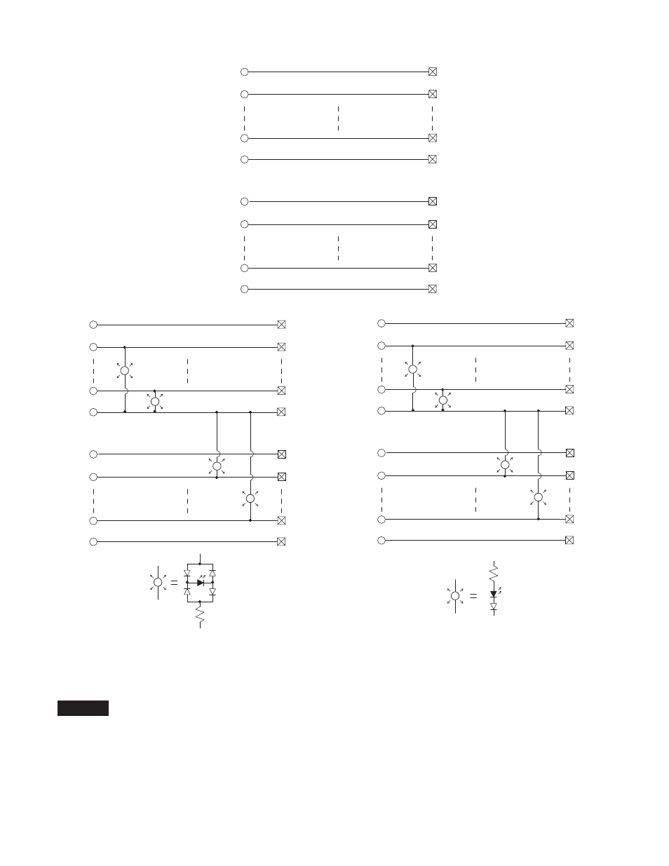
1492-IFM20FN
1492-RIFM20N
1492-IFM20FNH
1492-RIFM20FNH
Pinout
Brochage
Anschlußbelegung
Disposizione
dei piedini
Esquema de pins
B1
B2
B9
2
11
18
B10
20
A2
A9
3
10
A1
1
A10
19
1492-IFM20D24N
B1
B2
B9
2
11
18
B10
20
A2
A9
3
10
A1
1
A10
19
LED Circuit
Circuit du LED
LED-Stromkreis
Circuito del LED
1492-IFM20D120N
B1
B2
B9
2
11
18
B10
20
A2
A9
3
10
A1
1
A10
19
LED Circuit
Circuit du LED
LED-Stromkreis
Circuito del LED
I/O Wiring Data
NOTICE
Wiring information for your I/O module, AIFM module and cable (e.g. wiring diagram and pinouts)are available online at www.rockwellautomation.com/en/e-tools.
To obtain information follow this procedure.
1) In the Catalog Number BOX at the above online site type in the catalog number of the IFM, AIFM, etc. module you are using and click on Submit.
2) At the next screen displayed, click on the Modify key (lower left of screen).
3) Click on the areas that indicate NO SELECTION and enter your specific configuration information (e.g. I/O platform, I/O MODULE, ETC.).
NOTE: To obtain the wiring diagram, you must select th Pre-Wired Cable Connector selection.
4) Configure your 1492 cable by filing in the NO SELECTION areas.
5) Click on the ACCEPT key for the configured 1492 cable. At the next screen click on ACCEPT for the 1492 module.
6) The next screen (Configuration Results) displays the results of your specific configuration. The "supplementary Documents" column contains I/O wiring information
for the configuration (e.g. I/O Wiring Diagrams).