Install air flow transmitter, Wire and connect air flow transmitter – Rockwell Automation 1414-IFZ35FGDAA Air Flow Transmitter User Manual
Page 3
Air Flow Transmitter 3
Publication 1414-IN001A-EN-P - October 2005
Install Air Flow Transmitter
The transmitter is mounted in such a way that the airflow passes the sensor head.
The power supply cables to the transmitter should be kept separated from high
voltage lines where heavy transients may occur.
The transmitter can be mounted in airflow channels with a diameter or channel
width of 100 to 370 mm (4 in to 15 in)
Wire and Connect Air Flow Transmitter
The length of the cable is not critical. Avoid placing it in parallel with other cables,
which may induce electrical noise on the voltage signal and thus disturb the
function of the transmitter.
The best installation is obtained with a separate cable to the transmitter. It is
recommended to use a shielded cable to the transmitter as this improves immunity
against noise when it is used in light-industrial areas. The shield should be
terminated at the supply point but not terminated at the transmitter.
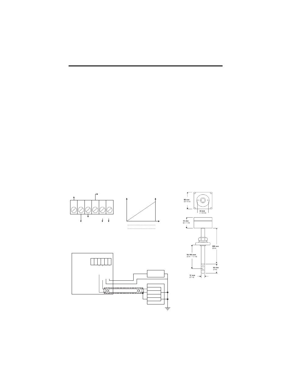
6 5 4
3 2 1
- +
24 VAC
16-30 VDC
Flow 4-20Ma
GRD
Flow 0-10VDC
Temp 0-10VDC
20
4
10
16 m/s (3150 ft/min)
8 m/s (1575 ft/min)
0
0
mA
V out(dc)
1
3
2
4
6
5
+ 24 VDC -
ANL IN 0 +
ANL IN 0 -
Analog Current Input
ANL COM
Loop power supply
F
lo
w
, 4-
20
m
A
Te
m
p
0
-1
0
V
F
low
, 0-
1
0
V
G
ro
und
Po
w
e
r
2
4
VAC
,
16
-3
0
V
D
C
- +
Air Flow Transmitter
Wiring Diagram
Output Signals Scales
Dimensions
Wire to a Programmable Controller