Heavy duty dynamic braking 25 – Rockwell Automation 1336_S_F_T Allen-Bradley Dynamic Braking User Manual
Page 25
Heavy Duty Dynamic Braking
25
1336-5.64 — July, 2005
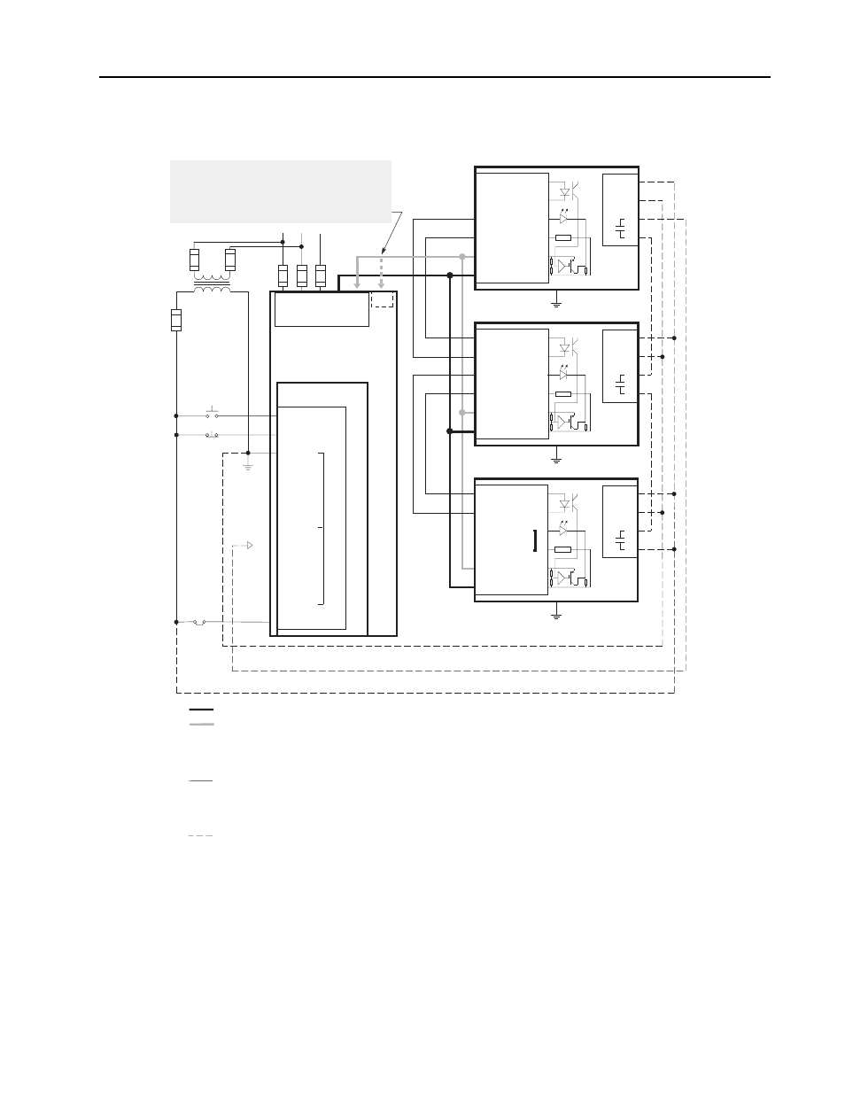
KA005-KA010, KB005-KB010 and KC005-KC010
Wiring Scheme
L1
L2
L3 +DC -DC
TB1
Drive
TB3
MOD-L3 or L6
20
STOP
19
START
START
115V AC
21
COM
22
23
24
➊
25
COM
26
27
28
29
COM
30
ENABLE
STOP
CUSTOMER
ENABLE
2
(–) SLAVE IN.
1
(+) SLAVE IN.
4
(+) MASTER OUT
5
(–) DC BUS
3
(–) MASTER OUT
TB1
Slave
Brake
6
(+) DC BUS
1
3
4
2
TB3
➌
➋
2
(–) SLAVE IN.
1
(+) SLAVE IN.
4
(+) MASTER OUT
5
(–) DC BUS
3
(–) MASTER OUT
TB1
Master
Brake
6
(+) DC BUS
1
3
4
2
TB3
➌
➋
➍
➍
Brake Power Wiring
Brake Power Wiring
All DC Brake Power Wiring must be twisted pair and run in conduit separate from Control Wiring.
Minimum required DC Brake Power Wiring sizes are listed in
tables 1b
,
2b
and
3b
.
Control Wiring
All Control Wiring must be twisted pair and run in conduit separate from DC Brake Power Wiring.
Interconnection Control Wiring between the brake terminals must be twisted pair, 1
mm
2
(18
AWG) minimum.
Optional Brake Fault Contact Wiring
A separate 115V
AC power supply is required if the brake fault contacts are to be monitored.
Refer to your 1336, 1336VT, 1336
PLUS, or 1336
FORCE User Manual for wire selection and installation details.
Connect to AUX at TB3 — Terminal 24 for L6 Option — Terminal 28 for L3 Option.
The MASTER OUT terminals are factory jumpered and must remain jumpered for single brake applications.
For multiple brake applications, remove the jumpers in all but the last enclosure.
Contact is shown in a de-energized state. Contact is closed when 115V AC power is applied to TB3 and pilot relay is energized.
Loss of power or a brake malfunction will open contact.
Connect the brake frame to earth ground. Refer to the connected drive's User Manual for grounding instructions.
➊
➋
➌
➍
-BRK
Important:
Series A 1336 PLUS (A4 frames)
380-480V, 5.5-7.5
kW/7,5-10
HP, do not use the
-DC terminal for brake connection. A separate -BRK
terminal is supplied for proper brake connection.
2
(–) SLAVE IN.
1
(+) SLAVE IN.
4
(+) MASTER OUT
5
(–) DC BUS
3
(–) MASTER OUT
TB1
Slave
Brake
6
(+) DC BUS
1
3
4
2
TB3
➌
➋
➍