Specifications spécifications, Technische daten specifiche especificaciones, I/o wiring data – Rockwell Automation 1492-IFMxxx Fusible Interface Modules User Manual
Page 4
Specifications
Spécifications
1492-IFM20F-F-2
1492-RIFM20F-F-2
1492-IFM20F-F24-2
1492-RIFM20F-F24-2
1492-IFM20F-F120-2
1492-RIFM20F-F120-2
1492-IFM40F-F-2
1492-IFM40F-F24-2
1492-RIFM40F-F24-2
1492-IFM40F-F120-2
2 Amps
12 Amps
0° C - 60° C
0 - 132V AC/DC
10 - 30V AC/DC
85 - 132V AC
Indicator Circuit Current
Courant circuit voyants
Strom, Anzeigeschaltkreis
Corrente circuito indicatori
Intensidad del circuito
de indicadores
Current/Circuit
Courant/Circuit
Strom/Schaltkreis
Corrente/circuito
Intensidad/circuito
Current/Module
Courant/Module
Strom/Modul
Corrente/modulo
Intensidad/módulo
Voltage Range
Tension
Spannung
Tensione
Voltaje
Catalog No.
Référence
Bestell-Nr.
N. Catalogo
Referencia
1492-IFM20F-F-2
1492-RIFM20F-F-2
1492-IFM20F-F24-2
1492-RIFM20F-F24-2
1492-IFM20F-F120-2
1492-RIFM20F-F120-2
1492-IFM40F-F-2
1492-IFM40F-F24-2
1492-RIFM40F-F24-2
1492-IFM40F-F120-2
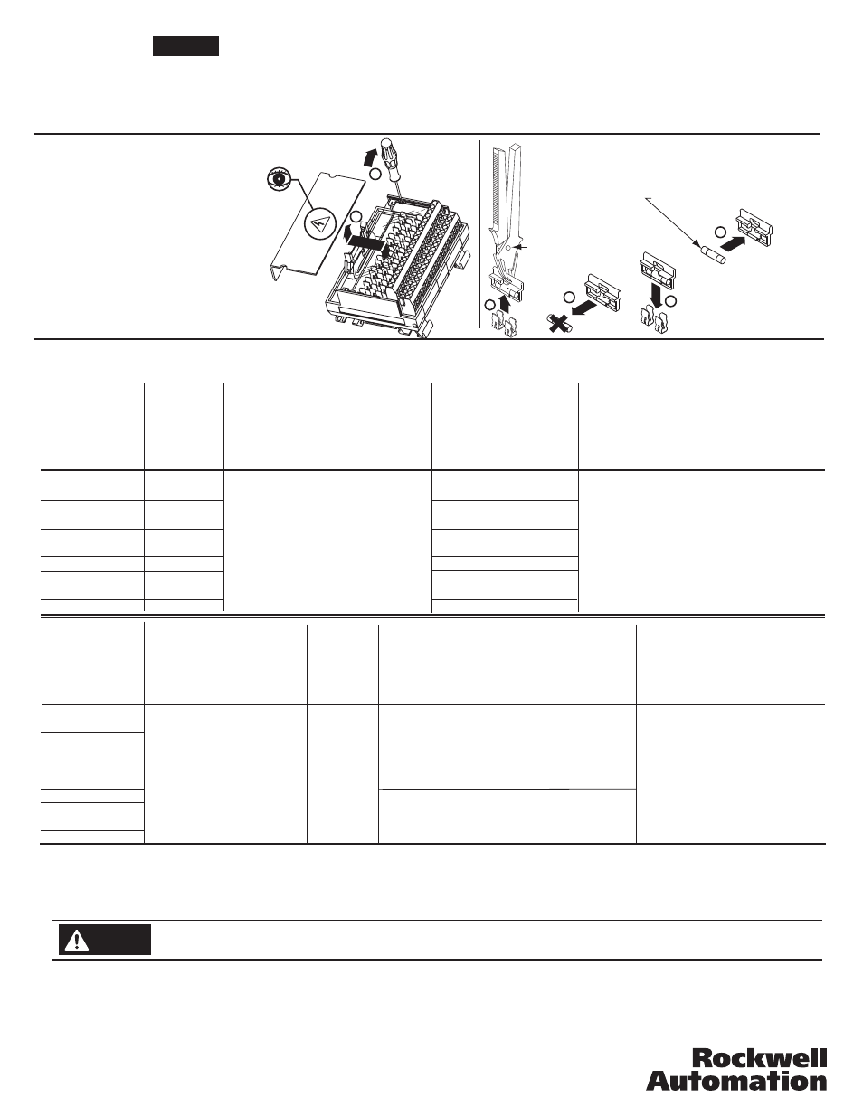
Fuse Installation/Removal
Installation/retrait des fusibles
Ein- und Ausbau der Sicherung
Montaggio/smontaggio dei fusibili
Instalación/extracción de fusibles
1
2
2
3
4
5 x 20 mm
(max. 2.0A per output; 12A per module)
(2,0 A par sortie maximum; 12 A par module)
(max. 2,0 A je Ausgang, 12 A je Modul)
(max 2 A per uscita; 12 A per modulo)
(2,0 A máx. por salida; 12 A por módulo)
1
GOULD 34-015G
LITTELFUSE 097023
BUSSMAN FP-A3
Technische Daten
Specifiche
Especificaciones
0 - 132V AC/DC
10 - 30V AC/DC
85 - 132V AC
N/A
2.0mA
2.5mA
N/A
2.0mA
2.5mA
Reference Publications: Refer to 1770-4.1 and appropriate PLC I/O module installation manual.
4.33 in. (110 mm) W
3.27 in. (83 mm) H
2.74 in (70.5 mm) D
8.27 in. (210 mm) W
3.27 in. (83 mm) H
2.74 in (70.5 mm) D
.76 lb.
(344 g.)
1.1 lb.
(520 g.)
Dimensions
Dimensions
Abmessungen
Dimensioni
Dimensiones
Humidity
Humidité
Feuchtigkeit
Humedad
Umidità
Operating Temperature Range
Plage températures de fonctionnement
Betriebstemperaturbereich
Limiti temperatura di funzionamento
Rango de temperatura de funcionamient
5 - 95%
Maximum Recurring Peak Voltage
Tension de crele réurrente maximale
Maximale periodische Hochstspannung
Tensione massima di cresta ricorrente
Voltaje de cresta iterativo máximo
600 V
p
cULus (File: E10314, Guide No. NRAG)
Suitable for use in Class 1 Div 2 Groups A,
B, C and D Hazardous and Non-Hazardous
Locations.
Temperature Code = T3C at 60°C
CE: Compliant for all applicable directives
FM Class 1 Div 2 Groups A, B, C and D
Temperature Rating T3C = 60°C
(J.I. 3000590, all except relay modules)
For transients > 600 Vp use a UL recognized suppression device rated at 2.5 kV withstand.
Pour des transitoires > 600 Vp utilisez un dispositif de suppression certifié UL à 2,5 kV nominal de tenue.
Für Einschaltstöße > 600 Vp verwenden Sie einen UL anerkannten Entstörer, der bewertet wurde bei 2,5 kV standzuhalten.
Per transitori > 600 Vp usare dispositivo di soppressione riconosciuto da UL capace di sopportare 2,5 kV.
Para transitorios > 600 Vp use un dispositivo de supresión reconocido UL clasificado con 2,5 kV.
Power, input and output (I/O) wiring must be in accordance with Class I Division 2 wiring methods - Artticle 501-10(B)(1) of the National Ele
Add 0.39 in. to the width dimension for 1492-Rxx type modules.
Wiring information for your I/O module, AIFM module and cable (e.g. wiring diagram and pinouts)are available online at www.rockwellautomation.com/en/e-tools.
To obtain information follow this procedure.
1) In the Catalog Number BOX at the above online site type in the catalog number of the IFM, AIFM, etc. module you are using and click on Submit.
2) At the next screen displayed, click on the Modify key (lower left of screen).
3) Click on the areas that indicate NO SELECTION and enter your specific configuration information (e.g. I/O platform, I/O MODULE, ETC.).
NOTE: To obtain the wiring diagram, you must select th Pre-Wired Cable Connector selection.
4) Configure your 1492 cable by filing in the NO SELECTION areas.
5) Click on the ACCEPT key for the configured 1492 cable. At the next screen click on ACCEPT for the 1492 module.
6) The next screen (Configuration Results) displays the results of your specific configuration. The "supplementary Documents" column contains I/O wiring information
for the configuration (e.g. I/O Wiring Diagrams). configuration (e.g. I/O Wiring Diagrams).
Non-condensing
Sans condensation
Nicht kondensierend
Senza condensa
sin condensación
I/O Wiring Data
NOTICE
Approx. Shipping Weight
Poids d'embarquement approximatif
Ungefähres Versandgewicht
Peso approssimativo del carico
Peso aproximado al momento de
embarque
Catalog No.
Référence
Bestell-Nr.
N. Catalogo
Referencia
Standards
Normes
Standards
Standard
Estándares
WARNING
Explosion Hazard - substitution of components may impair suitability for Class I Division 2.
Explosion Hazard - Do Not Disconnect Equipment unless power has been switched off or the area is known to be Non-Hazardous.
SURGE SUPPRESSION follow the literature recommendations of the PLC module being used.
La section SUPPRESSION DES SURTENSIONS se trouve à la suite de la littérature qui contient les recommandations relatives au module PLC utilisé.
ÜBERSPANNUNGSSCHUTZ Bitte beachten Sie die Dokumentationsempfehlungen für das jeweils benutzte SPS-Modul.
Per la SOPPRESSIONE DEI PICCHI TEMPORANEI, seguire le istruzioni riportate nella documentazione in dotazione al Modulo PLC utilizzato.
SUPRESIÓN DE SOBRETENSIÓN, siga las recomendaciones indicadas en la documentación del módulo PLC respectivo.
PN-23116
DIR 40063-257 (Version 12)
Printed in U.S.A.