Assembly method number 1, Auxiliary kit installation – Rockwell Automation 1494 Multiple Door Interlock Method of Assembly - Instructions User Manual
Page 3
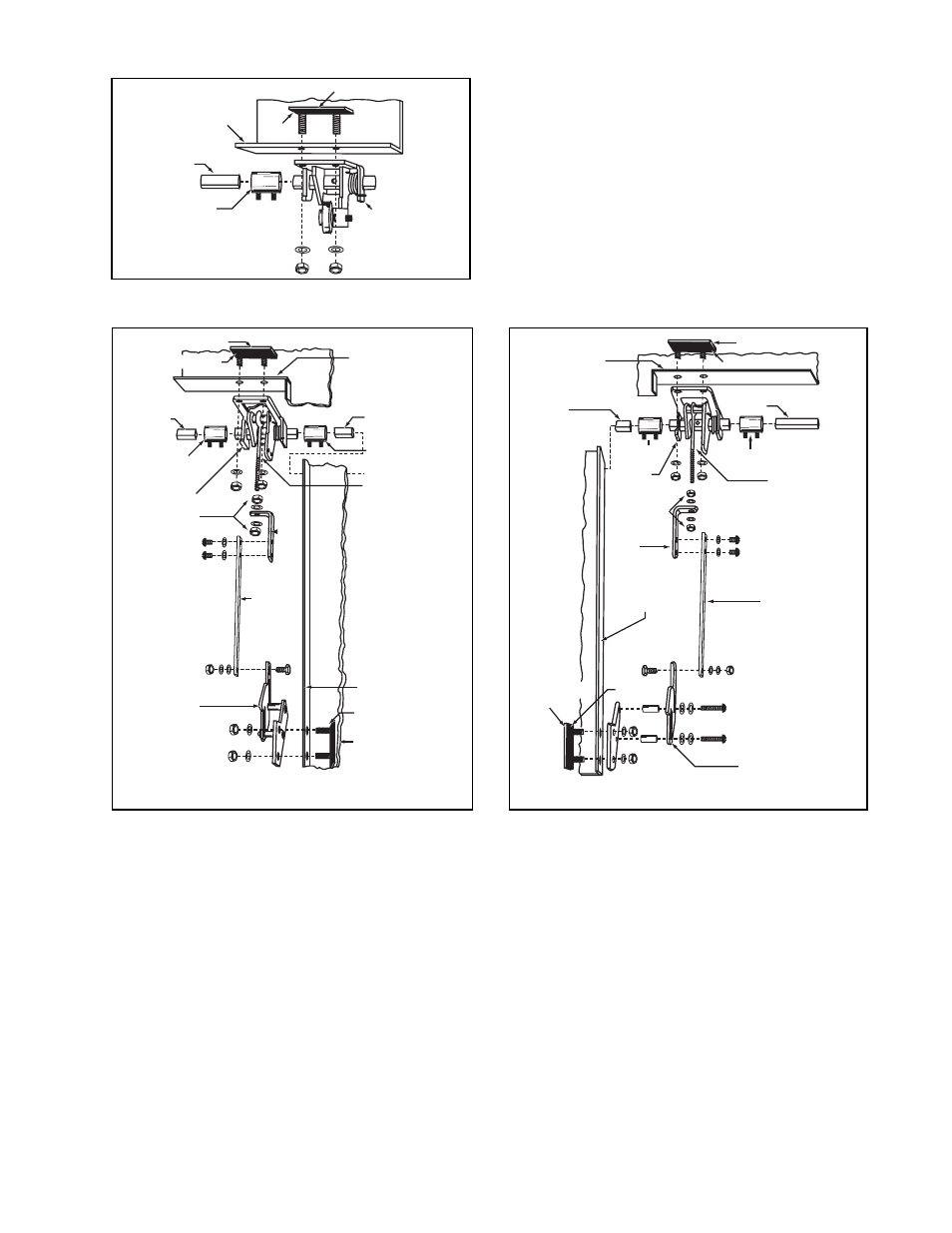
ASSEMBLY METHOD NUMBER 1
Master Interlock Installation
1.
Remove nuts and washers from mounting plate.
2.
Place the mounting plate studs through the holes in
the enclosure’s upper flange lip and the master inter-
lock, as shown in the figure to the left, and secure
assembly to flange.
3.
Attach the coupling to the master interlock as indi-
cated.
NOTE: The Master Interlock Assembly should be exactly
at a right angle with the enclosure side flange lip. Other-
wise binding could result.
AUXILIARY KIT INSTALLATION
Upper Operator Assembly
1.
Remove nuts and washers from upper operator
mounting plate.
2.
Place the mounting plate studs through the holes in
the enclosure upper flange lip and the upper operator,
as shown in Figure 5 or 6, and secure assembly to
flange with nuts tightened to 40…50 lb-in. torque.
NOTE: The Upper Operator Assembly should be exactly
at a right angle with the enclosure side flange lip. Other-
wise, binding could result.
3.
Fasten the Connecting Rod(s) between Master and
Auxiliary Kit(s) as indicated in the figures above and
on page 3. Tighten coupling screws to 24…32
lb-in. torque.
Lower Operator Assembly
1.
Remove nuts and washers from side mounting plate.
2.
LEFT-HAND AUXILIARY KIT ONLY: Disassemble
lower operator and reassemble as shown in Figure 6.
Tighten the screws to 24…32 lb-in. torque.
3.
Place the mounting plate studs through the holes in
the enclosure’s side flange lip and auxiliary kit lower
operator mechanism, as shown, and secure to flange
with nuts tightened to 40…50 lb-in. torque.
4.
Attach the Lifting Rod to the upper and lower auxiliary
kit operator(s) as indicated, using a torque of
24…32 lb-in. for the shoulder screw and the screws
used to connect to the link.
Mounting Plate
Gasket
Enclosure Upper
Flange Lip
Connecting
Rod
Coupling
Figure 4
Master
Interlock
Connecting
Rod
Coupling
Eye Bolt
Gasket
Mounting
Plate
Enclosure Side
Flange Lip
Connecting
Rod
Coupling
Upper
Operator
Adjusting
Nuts
Link
Right-Hand Auxiliary
Mounting Plate
Gasket
Enclosure Upper
Flange Lip
Lower
Operator
Lifting
Rod
Figure 5
Enclosure Upper
Flange Lip
Connecting
Rod
Coupling
Upper
Operator
Adjusting
Nuts
Link
Enclosure Side
Flange Lip
Mounting
Plate
Gasket
Lower Operator
Lifting
Rod
Eye Bolt
Coupling
Connecting
Rod
Left-Hand Auxiliary
Figure 6
Gasket
Mounting Plate