Rockwell Automation 1326AB, 1394, 842A Absolute Encoder Feedback Adapter Kit User Manual
Page 2
2
1326AB Absolute Encoder Feedback Mounting Adapter Kit
Publication 1326A-5.29 February 2000
Installing the Encoder Feedback
Mounting Adapter Kit
Important: This adapter is designed to accept Allen-Bradley 842A
encoders only.
To install the encoder feedback mounting adapter kit:
1. Remove the back plate and gasket from the end of the motor
(discard the old gasket). Refer to Figure 3 for an overview of the
installation.
2. Thoroughly clean the shafts, coupling bores, and mounting faces
to remove oil or any other substance that may be present.
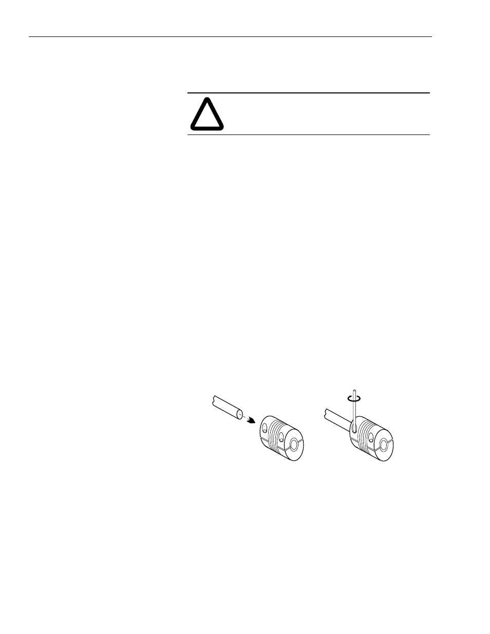
3. Using the allen wrench supplied in the kit, attach the flexible
coupling to the stub shaft of the motor (refer to Figure 1 below).
When tightening, use no more than 1.8-2.0 N-m (16-18 lb-in.) of
torque. The shaft must be visible through the spacings in the
coupling.
Important: The flexible coupling contains an insulating sleeve
on one end. The sleeve guards against motor
generated heat migrating to the encoder. The
coupling end with the insulating sleeve must be
positioned towards the encoder.
Figure 1
Attaching the Coupling to Motor Shaft
Important: The coupling is a flexible type that must be installed
in a relaxed state (not compressed or stretched).
Installation in the compressed state will limit the
ability of the coupling to flex adequately.
Installation in a stretched condition might exceed
the couplings yield point when flexed. Either
condition will shorten the life of the coupling.
4. Attach the encoder to the adapter using the screws supplied.
Tighten the screws using no more than 2.3-2.8 N-m (20-25 lb-in.)
of torque.
!
ATTENTION: To avoid a shock hazard, ensure that
all power to the motor is removed before installing the
adapter.
Coupling
Motor Shaft