Rockwell Automation 1325R Small DC Motors User Manual User Manual
Page 4
4
Small DC Motors
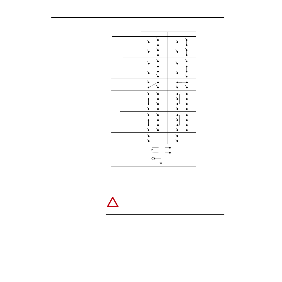
Connection diagrams are shown above. Care must be taken to ensure that
the dual-voltage shunt field is properly connected.
Some DC motors are equipped with a thermostat inside the motor. This
thermostat has a normally closed (NC) contact which opens if the motor
temperature exceeds design limits due to extended overload operation.
Leads from the thermostat are labeled P1 & P2 and should be connected in
series with the drive “STOP” button (refer to the previous figure).
!
ATTENTION: Ground the machine properly to avoid serious
injury to personnel. Grounding should be in accordance with the
National Electrical Code and consistent with sound local
practices.
+A1
High
Voltage
Connection
1, 2
Low
Voltage
Connection
1, 2
High
Voltage
Connection
1, 2
Low
Voltage
Connection
1, 2
Permanent
Magnet
Thermostat
(if furnished)
Ground
Connection
Connect in Series
with Control Stop
Device
Earth Ground
Series
A2
S1
+F1
F11
F2
A1
+A2
S1
+F1
F11
F2
+A1
A2
S1
–S2
+F1
F11
F2
A1
+A2
S1
+F1
F11
F2
S2
F22
S2
F22
F22
–S2
F22
+A1
Type
Shunt
Stabilized Shunt and Compound
CCW
Rotation Facing Commutator End
CW
–A2
+F1
F11
–F2
+A1
A2
S1
S2
A1
+A2
S1
S2
F22
+A1
–A2
–A1
–A1
+A2
+F1
F11
–F2
F22
+A1
A2
+F1
F11
F2
F22
–A1
+A2
+F1
F11
F2
F22
+A2
P1
P2
1
Motors with single voltage fields do not have leads F11 & F22. Leads F11 & F22 may be
marked F3 & F4, respectively. Connect on low voltage field connection.
2
Consult motor nameplate to determine value of low and high voltage connection.