Rockwell Automation 802B Compact Limit Switch User Manual
Rockwell Automation Equipment
1
Installation and Operating Instructions
Bulletin 802B Compact Limit Switch
IMPORTANT: SAVE THESE INSTRUCTIONS FOR FUTURE USE.
This publication does not include specifications, dimensions, and other installation considerations.
Refer to the product catalog pages for additional information.
!
WARNING:
To avoid electrical shock and/or unintended operation of equipment, disconnect all power to the limit
switch and the controlled equipment before proceeding with any repair or adjustment of the limit
switch.
Overview
Limit Switches are used in electrical control systems to sense
position. They are actuated by the predetermined motion of a
cam, machine component, or piece part. This mechanical
motion is then converted to an electrical signal through the
actuation of a set of contacts. These signals can be used in
the control circuits of solenoids, control relays, and motor
starters to control the operation of conveyors, hoists,
elevators, machine tools, etc. They are not to be used to
directly control a motor.
General Data
•
Enclosure Rating: NEMA 1,3,4,6,12,13 and IP67
•
Mechanical Life: Approx. 10,000,000 operations
Ê
•
Electrical Life: Approx. 200,000 operations (3A 250V AC,
resistive load)
Ê
•
Operating Speed
G
Top Push: 0.1mm to 0.5m per second
G
Side Rotary: 1mm to 1m per second
•
Operating Frequency:
G
Mechanical: 120 operations/minute
G
Electrical: 30 operations/minute
•
Operating Temperature: –10
°
C to 70
°
C (14
°
F to 158
°
F)
with no icing
•
Short Circuit Protection: Quick blow fuse suitable for rated
current is recommended.
Ê
Life expectancy has been calculated at an operating temperature
of 5
°
C to 35
°
C (41
°
F to 95
°
F) and an operating humidity of 40% to
70%.
Wiring
PreĆLeaded Models
COM
NO
NC
G
Black
Blue
Brown
Green/Yellow
AC QD Pin-out:
DC QD Pin-out:
Pin 1 = Common
2
Pin 1 = N/O
2
1
Pin 2 = N/O
2
1
4
3
Pin 2 = Common
4
3
2
1
Pin 3 = N/C
4
Pin 3 = Grnd.
M l R
t l
Pin 4 = Grnd.
Pin 4 = N/C
Male Receptacle
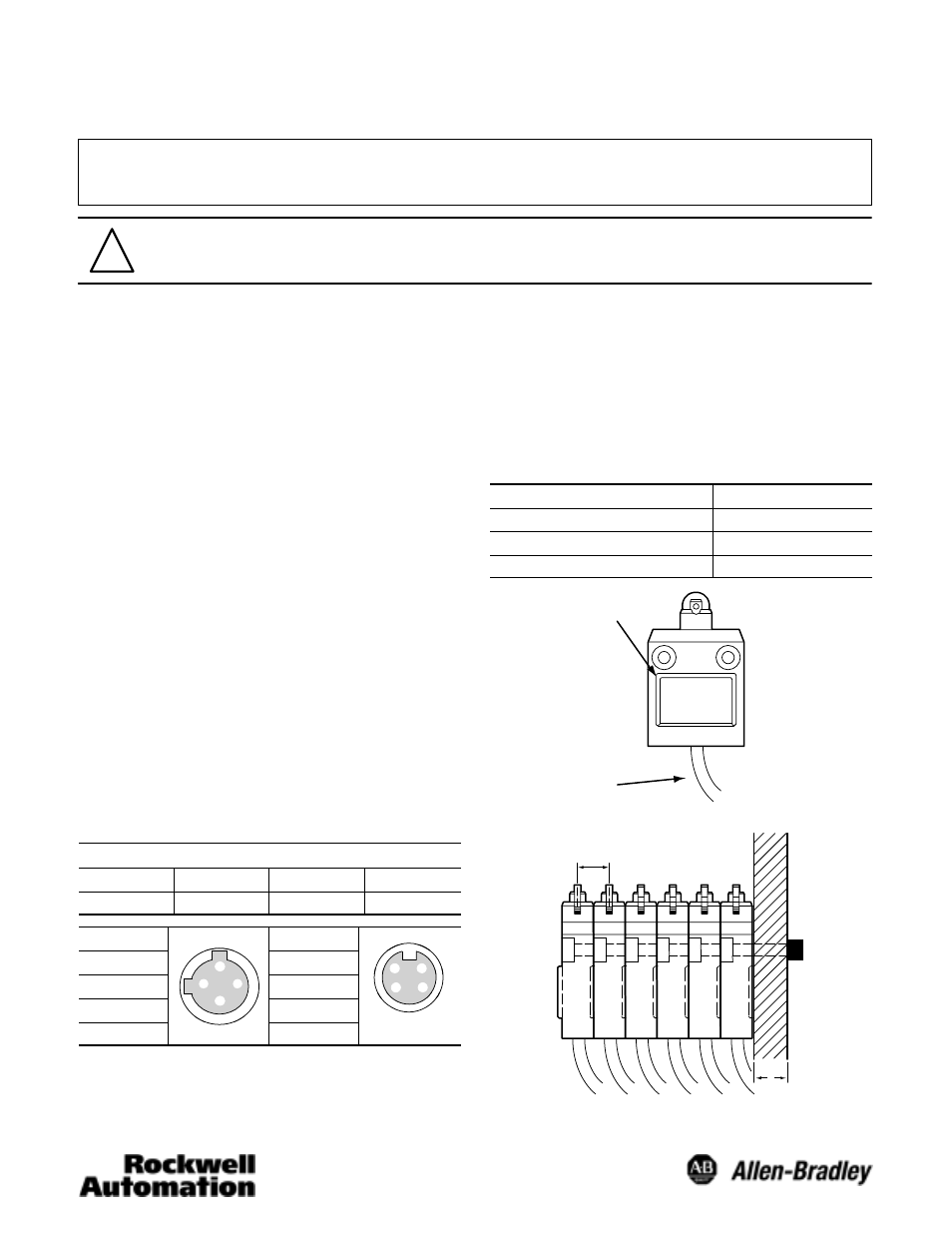
Mounting
Units should be mounted using the mounting holes provided.
These mounting holes are counter boarded to help contain
the bolt heads. The use of M5 Cap Screws, (Hex head), and
washers is recommended. Mounting bolts should be torqued
to a value between 4.90 and 5.88 Nm. These units have been
designed to enable gang mounting. In the case of ganged
mounting, the installer should fit the convex part of the gang
mount guide into the concave guide of the adjacent switch. A
maximum of six switches may be ganged. Special units that
have been designed for panel mounting will be provided with
a threaded head. These switches will also have washers and
a mounting nut included with the switch.
Hardware
Torque
Head mounting screw
0.78 to 0.88 N@m
Side rotary shaft bolt
4.90 to 5.88 N@m
Unit mounting screw
4.90 to 5.88 N@m
GangĆmounting guide
(convex front and
concave rear)
Mounting Panel
16mm
45mm
bend radius
6mm