Rockwell Automation 440P-WM1A Short Lever Installation/Operating Instructions User Manual
Rockwell Automation Equipment
Installation and Operating Instructions
Bulletin 440P-WM1 & 440P-WM1A Short Lever
IMPORTANT: SAVE THESE INSTRUCTIONS FOR FUTURE USE.
This publication does not include all specifications, dimensions, or any special installation considerations.
Refer to the product catalog pages for additional information.
General Data
• Designed for 440P-M short lever limit switches
• Metal or nylon roller available
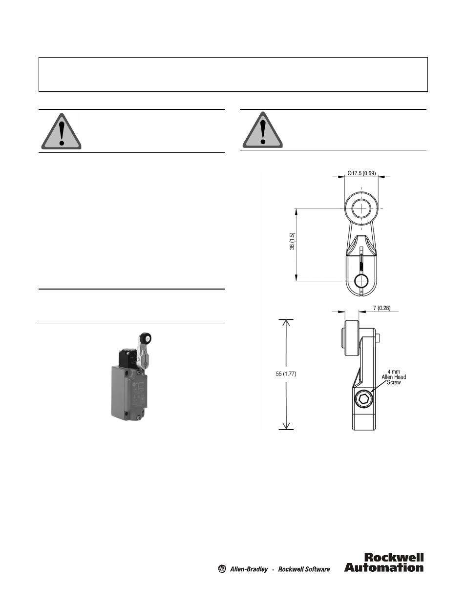
• Roller diameter 17.5 mm (0.69 in.) x width 7 mm (0.28 in.)
• Lever radius 35 mm (1.5 in.)
• Lever length 55 mm (1.77 in.)
• Includes Allen head screw
Principles, Standards, and Implementation
Operating specifications must be followed. Actuators should
be displaced beyond the point where direct opening action
occurs. If adjustable actuators become loose they may defeat
the direct opening action feature of the limit switch. These
devices are not to be used to directly control a motor.
ATTENTION: To avoid electrical shock and unintended
operation of equipment, disconnect all
power to the limit switch and the controlled
equipment before proceeding with any
repair or adjustment of the limit switch.
IMPORTANT: Installation of Allen-Bradley limit switches should be in
accordance with local and/or national codes. Servicing
energized industrial control equipment can be hazarous if
not in accordance to recommended safety procedures.
Short lever shown installed.
Approximate Dimensions [mm (in.)]
Instructions
1. Mount lever on shaft in desired position.
2. Torque Allen head screw to 1.5…2.1 N•m
(13.28…18.59 lb•in).
ATTENTION: For safety applications
Rockwell Automation recommends
replacing the complete limit switch.