Notice – Rockwell Automation 140U N-Frame CB Alarm Switch and Alarm Auxiliary Switch Combination User Manual
Page 2
Where local codes and standards permit and UL listing
is not required, internal accessories can be field
installed in sealed circuit breakers. In this case, UL list
i
ng becomes invalid and the label should be removed.
File E7819.
Before attempting to install the ASL switch or acces-
sory combination, check that the catalog number is
correct as ordered and that the rating of the acces-
sory(s) satisfies the job requirements.
Depending on the model ordered, connections for the
ASL switch and auxiliary switch contacts are in one of
four forms. The standard wiring configuration is pigtail
leads exiting the rear of the base directly behind the
accessory. Optional configurations include a terminal
block mounted on the same side of the base as the
accessory, leads exiting the side of the base where the
accessory is mounted, and leads exiting the rear of the
base on the side opposite the accessory. The 18-inch
long pigtail leads are color coded for identification; iden-
tification labels are provided for pigtail leads and termi-
nal block points. For allowable locations of all acces-
sories, refer to
Selection Guide.
No more than three pigtail leads can be routed
through the rear trough in the circuit breaker base.
This instruction leaflet (IL) gives detailed procedures for
installing the ASL switch and ASL switch/auxiliary switch
combination (accessory combination).
Table 1-1. Alarm (Signal)/Lockout and Auxiliary Switch
Electrical Rating Data
①➁➂
Maximum
Freq
Maximum
Dielectric
Voltage
Current
Withstand
(V)
(A)
Voltage (V)
600
50/60 Hz
6
2500
125
DC
0.5
➃
250
DC
0.25
➃
① Endurance- 400 electrical operations plus 5600
mechanical operations
➁ Pigtail wire size - No. 18 AWG (0.82 mm)
➂ Terminal block is listed for use with one or two No. 18 to
No. 14 AWG solid or stranded copper wires. Torque is
7 Ib-in (0.8 N.m)
➃ Non-inductive load
2. INSTALLATION
The ASL switch(es) and accessory combination can be
field-installed in N
-Frame circuit breakers.
Page 2
NOTICE
NOTICE
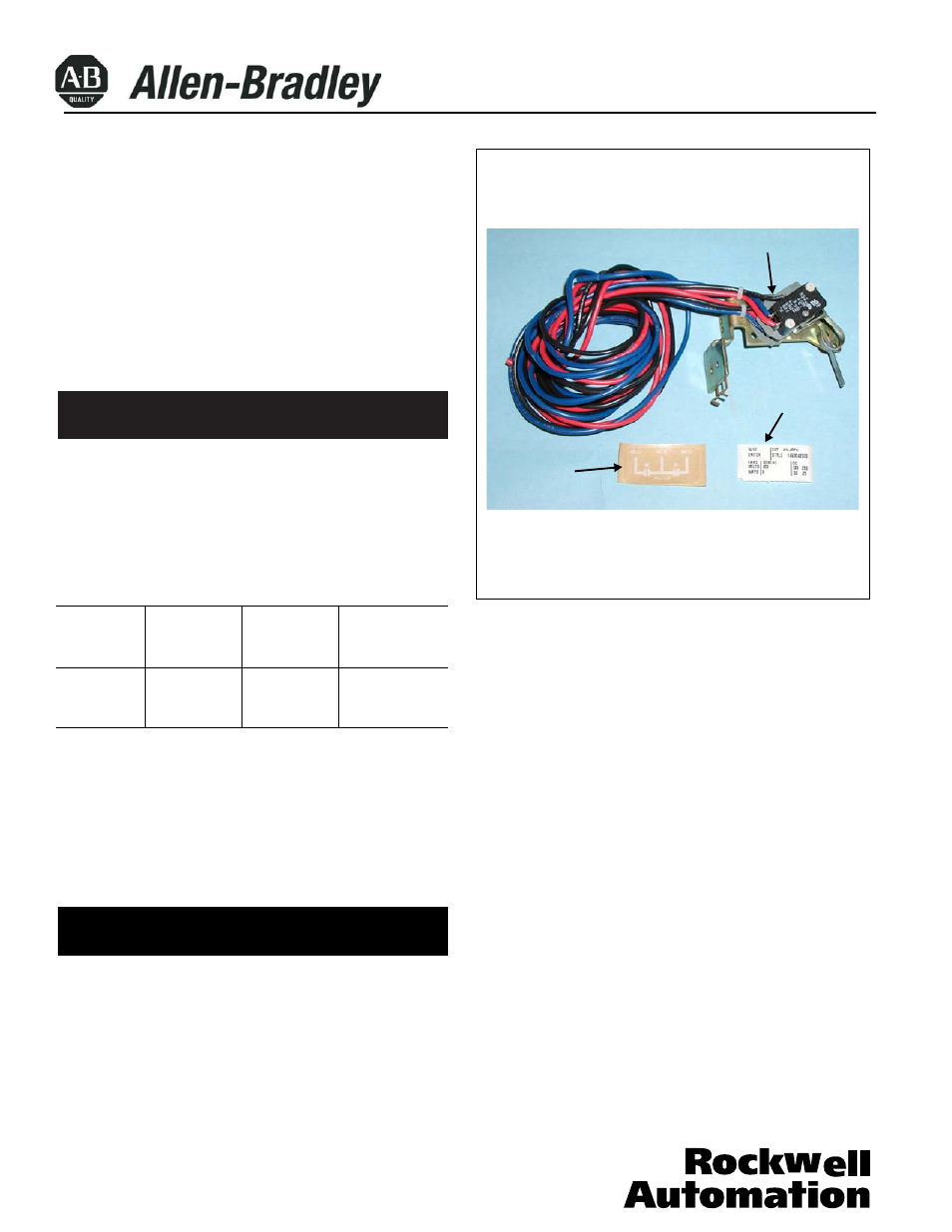
Fig. 2-1. Alarm (Signal) Lockout Switch Kit
40752-094 (1)
Effective 04/02
The ASL switch (shown in kit form in Fig. 2-1) and accessory
sory combination, is installed in the right or left accessory
mounting cavity of a 2-, 3-, or 4-pole circuit breaker. An
before the circuit breaker is mounted in an electrical sys-
tem. To install the auxiliary switch, perform the following
procedures:
auxiliary switch must be installed in the circuit breaker
Plug-in Module with
Pigtail Leads (single
ASL Switch Shown)
Accessory
Identification
Label
Connection
Diagram Label
(Pigtail Lead
Label Shown)