Rockwell Automation 440P-WM4 Metal Spring Rod Installation/Operating Instructions User Manual
Rockwell Automation Equipment
Installation and Operating Instructions
Bulletin 440P-WM4 Metal Spring Rod
IMPORTANT: SAVE THESE INSTRUCTIONS FOR FUTURE USE.
This publication does not include all specifications, dimensions, or any special installation considerations.
Refer to the product catalog pages for additional information.
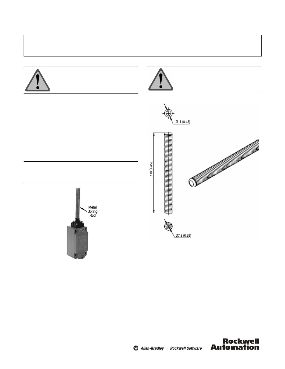
General Data
• Designed for 440P-M metal spring rod limit switches
• Spring rod diameter 11 mm (0.43 in.)
• Spring rod length 113 mm (4.45 in.)
Principles, Standards, and Implementation
Operating specifications must be followed. Actuators should
be displaced beyond the point where direct opening action
occurs. If adjustable actuators become loose they may defeat
the direct opening action feature of the limit switch. These
devices are not to be used to directly control a motor.
ATTENTION: To avoid electrical shock and unintended
operation of equipment, disconnect all
power to the limit switch and the controlled
equipment before proceeding with any
repair or adjustment of the limit switch.
IMPORTANT: Installation of Allen-Bradley limit switches should be in
accordance with local and/or national codes. Servicing
energized industrial control equipment can be hazarous if
not in accordance to recommended safety procedures.
Metal spring rod shown installed.
Approximate Dimensions [mm (in.)]
Instructions
1. Remove old spring rod by holding the rubber gasket at the
base of the spring rod and turning the spring rod counter-
clockwise.
2. Thread the replacement spring rod onto the threaded post
shaft extending vertically from the operator head.
3. While holding the rubber gasket at the base of the spring
rod torque the spring rod clockwise to 1…1.4 N•m
(8.85…12.39 lb•in).
ATTENTION: Operator heads with adjustable actuators
should
NOT be used for safety
applications.