Rockwell Automation 871P VersaCube User Manual
Page 2
Publication 77103–409–01(D)
November 1999
Printed in USA
Visit our web site at:
http://www.ab.com/sensors
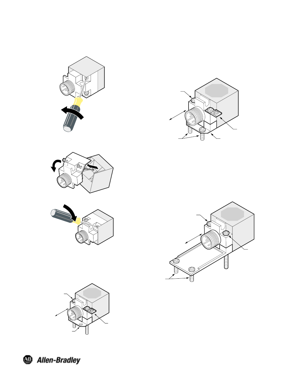
Changing Head Positions
To switch between top and side sensing head positions, follow
these three steps:
1. Unscrew the two #6–32 screws. Note: these screws are
captive. It is not necessary to remove them completely.
2. Pull head and mounting base gently apart and twist to new
position. Note: do not pull on connecting cable. Damage to
unit may result.
3. Re-install the two #6–32 screws and torque to 8–10 in-lbs.
Mounting and Adjustment Instructions
Mount the unit to a stable, flat surface as shown below. Use
the two #10–32 x 1 1/2
I
screws provided in the hardware kit.
The slotted mounting holes allow adjustment of sensing
position by sliding the unit back and forth before tightening the
screws.
Through-hole
Adaptor
Optional
Ground Lug
(Kit 871A–PKIT)
10–32 x 1 1/2
I
Mounting Screws
Adjustment
Direction
NOTE: Weld field immune models include 871A–PKIT.
Retrofitting Rectangular Models
Some rectangular-style proximity sensors have a hole pattern
which requires a threaded adaptor which is available with
screws in the 871A–PKIT. Mount the VersaCube to the
threaded adaptor using two #10–32 x 1
I
screws. Remove the
rectangular-style sensor and install the VersaCube and
bracket in its place as shown. The VersaCube’s slotted
mounting holes allow adjustment of the sensing position by
moving the unit backward or forward before tightening the
bracket screws.
Optional
Ground Lug
(Kit 871A–PKIT)
Adjustment
Direction
Mounting
Screw
10–32 x 1
I
Bracket Screws
Threaded
Adaptor
Retrofitting Limit Switch—Style Models
Limit switch style brackets are available for superior mounting
stability and convenience when retrofitting a limit switch-style
proximity sensor. Mount the VersaCube to the limit switch
bracket (871A–PKITLS) with one #10–32 x 1
I
screw. Remove
the limit switch-style proximity sensor and install the
VersaCube and bracket in its place as shown. The
VersaCube’s slotted mounting holes allow adjustment of the
sensing position by moving the unit backward or forward
before tightening the bracket screws.
Through-hole
Mounting
Adjustment
Direction
ounting
Screw
10–32 x 1
I
Bracket Screws