Installation, Dimensions — mm (inches) – Rockwell Automation 871L AC/DC Limit Switch Style Inductive User Manual
Page 2
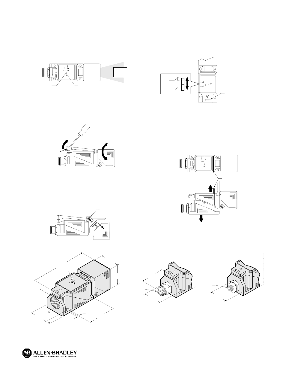
Installation
Alignment
When power is applied to the sensor, the green (power on)
indicator will turn on. Visually sight the sensing head at the
object to be detected until the orange (output energized)
indicator turns on when the sensor is set for normally open or
turns off when the control is set for normally closed.
Sensor (Top View)
Target
Orange
Green
Output Energized
Power On
Rotation of Sensing Head
Insert screwdriver in slot located at the bottom of the clear
plastic cover, gently pull upward. This will release the locking
mechanism and enable rotation of the sensing head. The
sensing head can be rotated in 15
°
increments.
Locking
Mechanism
Sensing Head Position
Unlock plastic cover and rotate sensing head so that clips are
in the top position. To change from side sensing to top
sensing, simply snap back the two clips located on either side
of the sensing head. Release and rotate the head to the top or
side position, return clips to locking position to secure head.
Clips Must be in
Top Posititon
Selecting Output
Insert screwdriver in slot located at the bottom of the clear
plastic cover, gently pull upward. This will release the locking
clip and allow access to the selectable output. The switch is
supplied in the normally open position. Simply move the
switch to the normally closed position; re-wiring is not
necessary.
(N.C.)
(N.O.)
Locking
Mechanism
Wiring of Terminal Base
Unlock the plastic cover to access the black bar. To release
the base, simply lift the black bar located inside the body. This
will release the locking mechanism. Gently pull the terminal
base from the sensor body to access the screw terminals.
Note: All external wiring should conform to the National Electric
Code and applicable local codes. See wiring diagrams
for external connections.
Black Bar
Dimensions — mm (inches)
120.0
(4.72)
40.0
(1.57)
40.0
(1.57)
60.0
(2.36)
7.3
(0.29)
Conduit
Entrance
1/2-14 NPT
15.9
(0.63)
30.0
(1.18)
LEDs
17.0
(0.67)
30.0
(1.18)
7/8Ć16UNĆ2A
Conduit Style
30.0
(1.18)
M12 x 1
Micro Style
Quick-Disconnect
Mini Style
Quick-Disconnect
Publication 46803–054–01(A)
November 1994
Printed in USA