Installation instructions – Rockwell Automation 802PR Inductive Proximity Sensor User Manual
Page 2
MOUNTING NEARBY METAL SURFACES
SPACING BETWEEN SENSORS
WARNING: Do not let METAL objects that are not to be
sensed come within three times the sensing distance of
this device. Unintended process activation may result in a
hazardous condition.
CAUTION: Solid state devices can be susceptible to radio frequency (RF) interference depending on the
frequency of the transmitting source. If RF transmitting equipment is to be used in the vicinity of the solid
state devices, thorough testing should be performed to assure that the transmitter operation is restricted to
a safe operating distance from the control equipment and wiring.
INSTALLATION INSTRUCTIONS
SERIES CONNECTED SWITCHES
PARALLEL CONNECTED SWITCHES
When connected in series, the operating
load voltage must be less than or equal to
the minimum supply voltage, minus the
voltage drops across the proximity switches
connected in series. The load will energize
when the connected outputs of all proximity
switches are energized.
To determine the maximum number of
switches for an application, the sum of the
maximum OFF--state currents of the
switches connected in parallel must be less
than the maximum OFF--state current of the
load device. The load will be energized when
the output of any proximity switch energizes.
NOTE: Parallel operation of switches does
not provide higher load current capability.
IMPORTANT: Save these instructions for future use. For
additional information and proper operating guidance, refer to
the Allen--Bradley Proximity Catalog 871--1.2.
Units may be mounted side-by-side. When mounting
face-to-face, use 1.8 times the diameter.
Shielded construction allows the proximity to be
mounted flush in surrounding metal, and may
increase the sensing distance.
HE
AD
ON
SE
NS
ING
DI
ST
ANCE
(INCH)
.10
.20
.30
.40
.50
(MIL
LI
METER
S)
2
4
6
8
10
12
14
SQUARE TARGET SIZE (X IN INCHES)
0.5
1.0
1.5
2.0
(MILLIMETERS)
10
20
30
40 50
X
X
0.062”
1
2
3
5
4
1
COLD ROLLED LOW CARBON STEEL
2
COLD ROLLED STAINLESS STEEL (AISI 304)
3
HALF HARD BRASS (ALLOY 260 ASTM B36)
4
ALUMINUM (ALLOY 1100-H14)
5
HALF HARD COLD ROLLED COPPER (ASTM B152)
1.8d
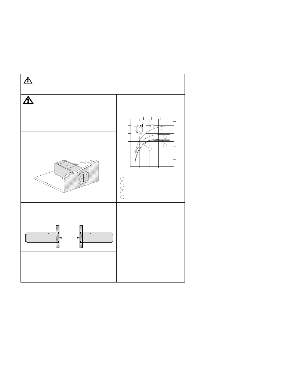
CHANGING POSITION OF HEAD
The sensing head can be positioned to face the front,
rear, or either side. Loosen the four screws on the top
of the switch, lift the head, and rotate the head to the
desired position. NOTE: Excessive twisting of the
connecting wires can result in damage.
SENSING DISTANCE
CORRECTION FACTORS
Printed in USA