Rockwell Automation 800T_H Pilot Devices User Manual
Page 2
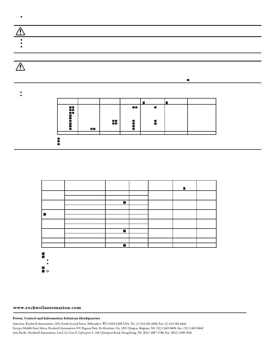
To determine the contact targets of Allen-Bradley 800T and 800H Momentary Push Buttons, 2 and 3 position Push-Pull Push Buttons, and 2 position Twist-release Push Buttons, proceed as follows.
1. Identify the CONTACT BLOCK used by looking at the contact block cover plate and finding a Catalog No. such as 800T-XA.
2. Identify the CIRCUIT for which the contact target is desired by looking again at the contact block cover plate for a wiring symbol such as “A”, “B”, “A1”, etc.
3. Refer to Fig 5 and find the contact block and wiring symbol.
Read across the top to find the Lens or Cap position. (IN, CENTER, or OUT)
The contact target is at the intersection of the contact block row and position column.
Dual Input Module Kits: 800T-N290 (120 Vac Full Voltage) Power module and lamp
800T-N291 (24 Vac Full Voltage) Power module and lamp
800T-N296 (120 Vac Transformer Type) Relay module.
Flashing Lamp (6V): 800T-N212 Available for any illuminated device which uses the ANSI No. 755 or No. 1866 lamp.
Lamp Installer: 800T-N82 Useful for installation or replacement of incandescent lamps
LED Lamps and Power Modules for extended lamp life:
(Consult A-B Catalog for ordering information)
The contact blocks listed below may be mounted in various combinations on an operator. See operator instruction sheet for any additional contact block limitations.
Two Tiers High Maximum (for mounting instructions see contact block instruction sheet)
Illuminated Push Button Operators Accept One (1) or Two (2) Contact blocks
Non-Illuminated Push Button Operators Accept One (1) to Four (4) Contact blocks
3 position Push-Pull Only
Using the NCLB Contact function on 2 position Push-Pull and 2 position Twist-Release causes the following:
When the button is pushed from the “OUT” to the “IN” position, the mechanical detent action of the operator occurs before the contacts change state.
When the button is pulled from the “IN” to the “OUT” position, the contacts change state before the mechanical detent action of the operator occurs.
800T-XA2 contact blocks must be used only on the second level if stacked.
Mini-blocks may be used on the second level only.
Sealed Switch blocks are not stackable and may be used one tier high maximum.
Standard Block
Cat. No. 800T/TC-
Self Monitoring
Cat. No. 800TC-
Mini-Block
Cat. No. 800T-
Sealed Switch Block
Cat. No. 800T-
Logic Reed Block
Cat. No. 800T-
Number of
Contacts
XA
XA1
XA2
XA4
XA7
XD1
XD2
XD3
XD4
7
–
–
–
–
–
–
–
–
XD4S
–
–
–
–
–
XD5
XD6
–
–
XAP
–
–
–
–
XD1P
XD2P
–
–
XAR
–
XA2R
XA4R
–
XD1R
XD2R
–
–
1 N.O.-1 N.C.
1 N.O.-1 N.C. (Late Break)
2 N.O.
2 N.C.
1 N.C.-1 N.C. (Late Break)
1 N.O.
1 N.C.
1 N.O. (Early Make)
1 N.C. (Late Break)
Series C or later
Series A or later
Series B or later
Series E or later
Series D or later
Series A or later
PenTUFF Block
Cat. No. 800T/TC-
XAV–
–
–
–
–
XD1V
XD2V
XD3V
XD4V
2 Circuit
Contact Block
Cat. No. 800T-
Single Circuit
Contact Block
Cat. No. 800T-
Normal
Circuit
Operation
Wiring
Symbol
OUT
Position
IN
Position
CENTER
Position
XA, XAR, XAP
XA1
XA2, XA2R
XA4, XA4R
XA7
–
–
XD2, XD6, XD2R, XD2P
XD1, XD5, XD1R, XD1P
XD1, XD5, XD1R, XD1P
XD1, XD5, XD1R, XD1P
XD1, XD5, XD1R, XD1P
XD4
XD4
XD3
XD4
N.C.
N.C.
N.C.
N.O.
N.O.
N.O.
N.O.
N.C.L.B.
N.C.L.B.
B
A
BZ
A1
A2
XD2, XD6, XD2R, XD2P
XD2, XD6, XD2R, XD2P
XD2, XD6, XD2R, XD2P
N.C.
B1
B2
BZ
N.O.E.M.
AZ
BZ
A
X
O
X
O
O
O
X
X
X
O
O
O
X
O
O
O
O
O
X
X
O
X
O
X
X
X
O
O
O
N.C.L.B.
B
X
O
O
X
X
X
O
4
8
8
Self Monitoring Block to be used only on 2 position devices. Only functional on level 1.
Contact blocks with normally closed contacts meet direct drive positive opening standard requirements when properly fused to IEC 269-1
and 269-2. Shallow/mini contacts: 10 A gl or N type cartridge fuse. PenTUFF contacts: 6 A gl or N type cartridge fuse.
Available Accessories for 800T and 800H Illuminated Device
Contact Blocks for 800T and 800H Push Buttons
Contact Target Table
Abbreviations and Symbols
NO = Normally Open NC = Normally Closed EM = Early Make LB = Late Break O = Open X = Closed
Fig. 5
Fig. 4
40061-052-01
DIR 40061-052
(Version 11)
Copyright © 2013 Rockwell Automation, Inc. All Rights Reserved. Printed in USA.
Allen-Bradley, Rockwell Software, and Rockwell Automation are trademarks of Rockwell Automation, Inc.
Trademarks not belonging to Rockwell Automation are property of their respective companies.
Publication
800T-IN004K-EN-E - April 2013
8
6 7
7 8
4
5
6
7
1
8
8
7
7
2 8
2 7
7
7
7
8
7
8
7
8
1 8
8
WARNING: Only
Sealed Switch and Logic Reed Blocks may be used on devices rated for Class I, Division 2 Hazardous Locations.
Substitution of the contact block may impair suitability for Division 2.
Exposure to some chemicals may degrade the sealing properties of materials used in the sealed contact blocks.
Normally Open (NO) contacts, sealed switch contact blocks and logic reed contact blocks can not be used for emergency stop control circuits.
WARNING: 800T-N296 is not rated for Class I Division 2 Hazardous Location.
5
5
5
3
3
3
1
2
3