Wiring diagrams, Approximate dimensions [mm (in.), Mounting space – Rockwell Automation 871F Proximity Sensors Installation Instructions User Manual
Page 2: Conduit style 1/2 inch npt, Conduit style pg13.5
PN-131512
10000222192 Ver 00
November 2011
Printed in USA
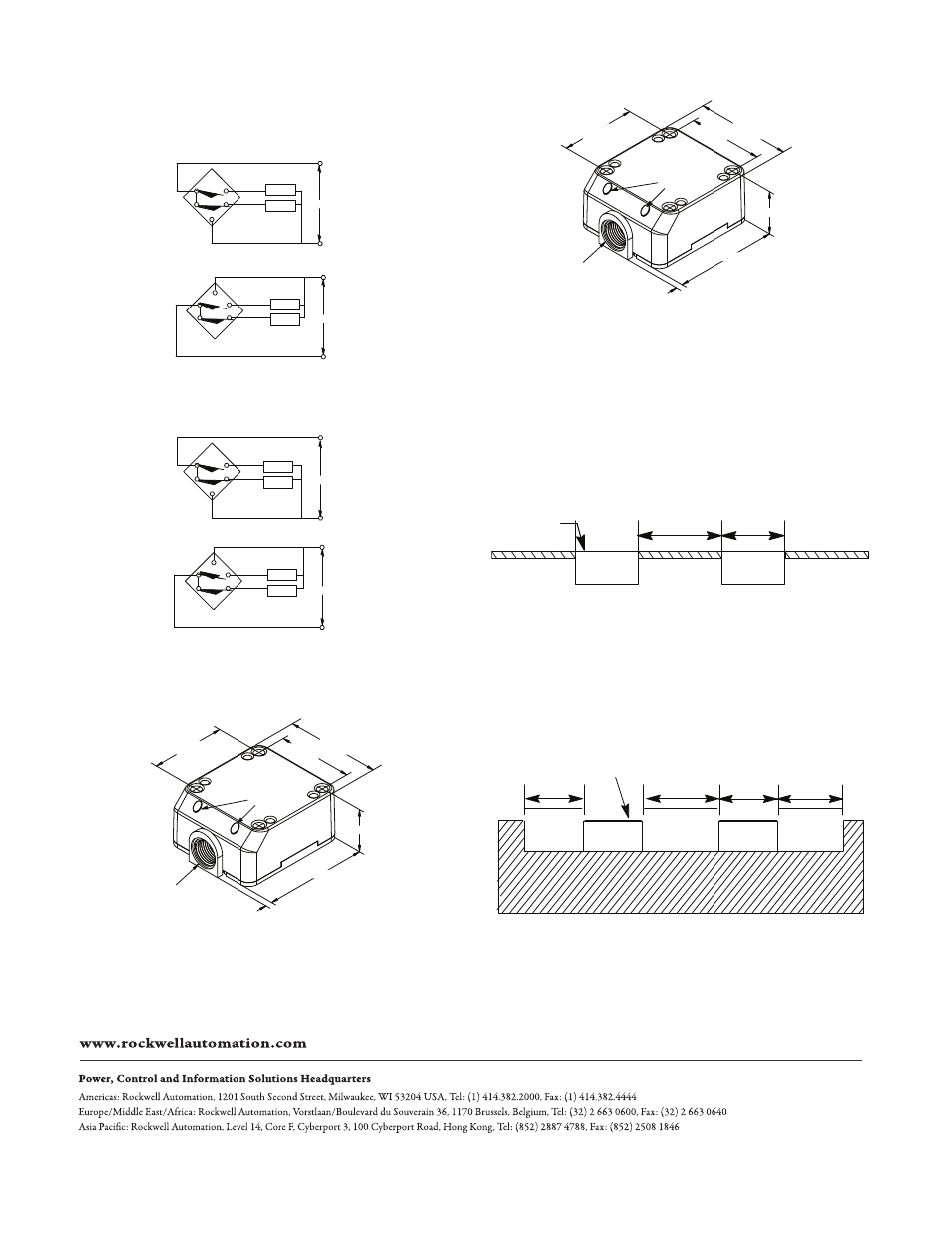
Wiring Diagrams
Conduit Style 1/2 inch NPT
Conduit Style PG13.5
Approximate Dimensions [mm (in.)]
Conduit Style 1/2 inch NPT
Suggested mounting: M5 or SAE#10 cap screw should be
used with a split lock washer to install the unit.
Complementary Normally Open and Normally Closed Outputs
PNP (Sourcing)
NPN (Sinking)
+
-
T4
T1
T5
T2
N.O.
+
-
N.C.
+
-
Load
Load
10…30V DC
+
-
T4
T2
T5
T1
N.O. +
-
N.C. +
-
10…30V DC
Load
Load
Complementary Normally Open and Normally Closed Outputs
PNP (Sourcing)
NPN (Sinking)
+
-
T4
T1
T5
T2
N.O.
+
-
N.C.
+
-
10…30V DC
Load
Load
+
-
T4
T2
T5
T1
N.O. +
-
N.C. +
-
10…30V DC
Load
Load
LEDs
65.0
(2.56)
44.0 (1.57)
83.0
(3.27)
65.0
(2.56)
6.0
(0.24)
94.0 (3.70)
Conduit opening
1/2 inch internal
thread
Conduit Style PG13.5
Mounting Space
Spacing Between Shielded Sensors (flush-
mountable) and Nearby Metal Surfaces
Shielded proximity sensors allow the electro-magnetic field to
be concentrated to the front of the sensor face. Shielded
construction allows the proximity to be mounted flush in
surrounding metal without causing a false trigger.
Flat Pack Style (871F)
Spacing Between Unshielded Sensors (nonflush-
mountable) and Nearby Metal Surfaces
Longer sensing distances can be obtained by using an
unshielded sensor. Unshielded proximity sensors require a
metal-free zone around the sensing face. Metal immediately
opposite the sensing face should be no closer than three
times the rated nominal sensing distance of the sensor.
Flat Pack Style (871F)
LEDs
44.0 (1.57)
94.0 (3.70)
6.0
(0.24)
83.0
(3.27)
65.0
(2.56)
65.0
(2.56)
Conduit opening
PG13.5 internal
thread
Active Face
d
d
d
d
d
4d
Active Face