Bulletin 156, Single phase multi-functional, Analog switching solid state contactor – Rockwell Automation 156-B50xV1 Single Phase Multi-Function Analog Solid State Contactor Operating Inst. User Manual
Page 2
~
~
- +
LOAD
4 - 20mA
2T1
1L1
5A3 3A1
4A2
6A4
~
~
LOAD
+ 10VDC
2T1
1L1
5A3 3A1
4A2
6A4
+
0V
24VDC/AC
-
0V
-
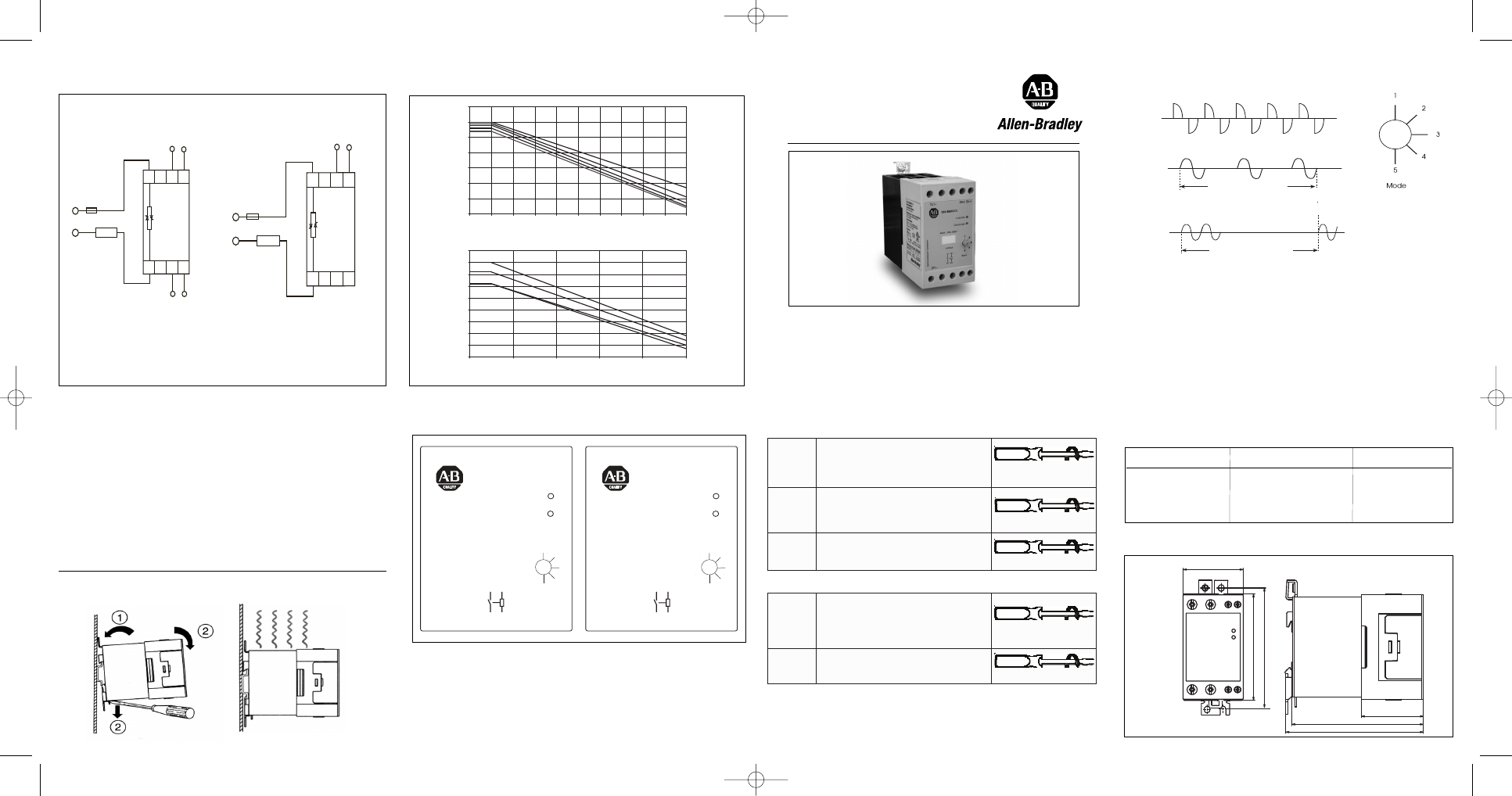
1 period = 64 cycles
1 period = 1s, 3s or 10s
MODE 1
MODE 2
MODE 3, 4, 5 - Burst 1s, 3s, 10s
Mode 1 ( Default)
: Phase Angle Switching |
Fasevinkel
kredsløbskobling
|
Phasenanschnittsteuerung | Conexión de
Ángulo de Fase | Commutation de l’angle de
phase | Phase Angle Switching
Mode 2: Distributed Control | Distribueret
kontrol
|
Vollwellensteuerung
|
Control
Distribuido | Trains d’ondes distribuées |
Distributed Full Cycle
Mode 3: Burst Switching (1 sec. period) |
Burst kredsløbskobling (1 sek. periode) |
Impulspaketsteuerung (1 s Periodendauer) |
Conexión del tren de pulsos (período de 1 s.)
| Trains d’ondes T.O.R. (période de 1 sec) |
Burst Switching ( 1 sec. period )
Mode 4: Burst Switching (3 sec. period) |
Burst kredsløbskobling (3 sek. periode) |
Impulspaketsteuerung (3 s Periodendauer) |
Conexión del tren de pulsos (período de 3 s.)
| Trains d’ondes T.O.R. (période de 3 sec) |
Burst Switching ( 3 sec. period )
Mode 5: Burst Switching (10 sec. period) |
Burst kredsløbskobling (10 sek. periode) |
Impulspaketsteuerung (10 s Periodendauer) |
Conexión del tren de pulsos (período de 10 s.)
| Trains d’ondes T.O.R. (période de 10 sec) |
Burst Switching ( 10 sec. period )
Note: • For the standard 156-B..V1, it is pos-
sible to have the ground terminals of the sup-
ply and control commoned externally and
connected to either terminal A2 or A3 only.
This is applicable for a 24V DC supply.
Note: • For standard 156-B..V1, kan man
anvende fælles jordklemmer til både forsyning
og kontrol af strøm. I så fald skal den fælles
jordklemme forbindes til enten klemme A2
eller klemme A3. Dette gælder kun, hvis 24
VDC forsyningsspænding anvendes.
Hinweis: • - Innerhalb des 156-B..V1 können
die Nulleiter der Spannungsversorgung extern
zusammengeführt werden und wahlweise an
den
Klemmen
A2
und-
/oder
A3
angeschlossen werden. Diese Möglichkeit ist
nur bei der 24Vdc Spannungsversorgung
möglich.
Note: • Pour la version standard 156-B..V1, il
est possible d'avoir la masse de l'alimentation
et de la commande communes en externe et
raccordée soit à la borne A 2 ou à la borne A
3. Ceci est applicable pour une alimentation
24 VCC.
Nota: • En el modelo estándar 156-B..V1 es
posible tener los terminales del común de la ali-
mentación A2 y del común de control A3 conec-
tados en el mismo común de la fuente externa de
alimentación, esto sólo se puede hacer cuando
se utiliza una tensión de alimentación de 24 VCC.
Note: • Per il modello standard 156-B..V1, è
possibile avere i terminali di terra, d' alimen-
tazione e di controllo esterni e collegati solo ai
terminali A2 o A3. Questo è applicabile per ali-
mentazioni a 24V CC.
3A1 - 5A3: Control Input Current
Example: 156-B..C1
3A1 - 5A3: Control Input Voltage, Vcc
4A2 - 6A4: Supply Input Voltage, Vss
Example: 156-B..V1
Analog Input
Supply
Analog Input
Connection Examples | Tilslutningseksempler | Anschlussbeispiele
Ejemplos de Conexión | Exemples de raccordement | Esempi di Connessioni
• Operating Instructions
• Kom godt i gang
• Betriebsanleitung
• Notice d'utilisation
• Instrucciones
• Istruzioni d’uso
Dimensions | Dimensioner| Dimensions | Abmessungen | Dimensioni | Dimensiones
45mm
91
.6
m
m
81
.7
m
m
103mm
46.5mm
Mounting | Montering | Montage | Anschlußbeispiel | Montaggio | Montaje
Mode Selection | Overføringsegenskaber | Sélection du Mode | Wahl der
Betriebsart | Selección de Modo | Selezione Commutazione
Transfer Characteristics | Overføringsegenskaber | Caractéristiques de transfert |
Übertragungscharakteristik | Características de Transferencia | Caratteristiche di Trasferimento
Terminal Layout | Terminalfordeling | Exemple de raccordement | Anschlußbeispiel |
Collegamenti Elettrici | Ejemplo de conexión
r
ot
c
at
n
o
C
r
ot
c
u
d
n
o
ci
m
e
S
Control ON
Load ON
3
A1+
5
A3-
AC51 : 50A, 600V
~
4-20mA
Mode
1
2
3
4
5
3A1 +
1L1
2T1 5A3 -
1
L1
~
2
T1
~
156-B50CC1
r
ot
c
at
n
o
C
r
ot
c
u
d
n
o
ci
m
e
S
Control ON
Load ON
3
A1+
6
A4+
5
A3-
4
A2-
AC51 : 50A, 230V
~
Vss: 24VAC/DC
Vcc: 0-10VDC
Mode
1
2
3
4
5
Vss
Vcc
3A1 +
1L1
2T1 5A3 -
1
L1
~
2
T1
~
156-B50AV1
Derating by Spacing | Laststrom in Abhängigkeit vom Geräteabstand | Derating by
Spacing | Curva de reducción | Riduzione delle prestazioni in base alla distanza tra i
disposittivi
L
o
a
d
C
u
rr
e
n
t
(A
A
C
rm
s
)
L
o
a
d
C
u
rr
e
n
t
(A
A
C
rm
s
)
Surrounding temperature (˚C)
Surrounding temperature (˚C)
20
25
30
35
40
45
50
55
60
65
70
20
30
40
50
60
70
35
30
25
20
15
10
5
0
55
50
45
40
35
30
25
20
15
10
RJ1P...30
RJ1P...50
22.5 mm
22.5/ 10.0 mm
6.0 mm
3.0 mm
0.0 mm
10.0 mm
6.0 mm
3.0/ 0.0 mm
156-B50..1
156-B30..1
1
5
6
-B
5
0
..
I_
1
4
0
5
0
9
7
6
8
0
4
1
7
Bulletin 156
Single Phase Multi-functional
Analog Switching Solid State Contactor
Control
Control
Output
Current (mA)
Voltage (VDC)
Power (%)
4
0
0
8
2.5
25
12
5
50
16
7.5
75
20
10
99
Output power as a function of control input
TERMINALS | TERMINALER | TERMINALES | BORNES | ANSCHLÜSSE | TERMINALI
To use 75˚C copper (CU) conductor only. |
Brug kun 75˚C kobbel kabler | Use sólo cables de
cobre a 75 ºC | Utiliser seulement des câbles âme cuivre de t° admissible 75°C |
Kupferanschlusskabel für 75°C | Utilizzare 75 ˚ C solo cavi in rame
L1, T1
Ground
Screw
Standard screw M5 x 8mm
(Screw not provided)
Min. 1 x 4mm
2
(1 x AWG12)
Max. 1 x 25 mm
2
(2 x AWG3)/
2 x10mm
2
(2 x AWG6)
2.5Nm with Posidrive 2 bit
A1, A2,
A3, A4
Min. 1 x 0.5mm
2
(1 x AWG20)
Max. 1 x 4mm
2
(1 x AWG12)/
2 x 2.5 mm
2
(2 x AWG14)
0.6Nm with Posidrive 0 bit
Max torque 2.5Nm
L1, T1
12 AWG - 3 AWG Str
12 AWG - 10 AWG Sol
2 x 10AWG Sol
2.5Nm with Posidrive 2 bit
A1, A2,
A3, A4
18 AWG - 12 AWG Str and Sol
2 x 14 AWG Str and Sol
0.6Nm with Posidrive 0 bit
IEC
UL
AB_RJ1P(150511).qxd:RJ1P_int3.qxd 5/22/11 11:34 AM Page 2