S5 = motor flc (full load current) configuration – Rockwell Automation 150-SM6 SMC-50 Soft Starter Parameter Configuration Option Module Installation User Manual
Page 4
PN-164974
DIR 10000152879 (Version 01)
Publication 150-IN053B-EN-E
S5 = Motor FLC (Full Load Current) Configuration:
Rotary Switch S
5
Position Setting
% of Controller’s Max FLC
(1)
(2)
0 40
(Default)
1 44
2 48
3 52
4 56
5 60
6 64
7 68
8 72
9 76
A 80
B 84
C 88
D 92
E 96
F 100
(1) Since a set of switches do not provide the resolution to enter all possible Motor FLC combinations like a keypad, Switch S5 allows you to configure the
Motor’s FLC in the SMC50 by using a percent (%) of the controllers raed (e.g 90A, 110A, 140A, 180A, etc) FLC.
-
Example: For a 60A motor and a 90A controller, the % of Controller’s max FLC for 60A would be 64% of 90A (57.6A) or switch position 6.
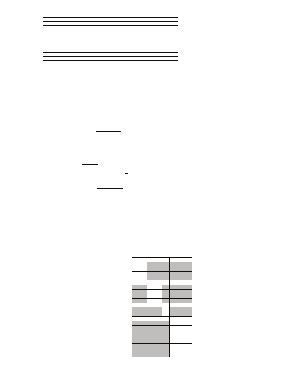
(2) To determine the S5 switch setting for an inside the delta motor configuration use the following 2 equations:
Motor Nameplate
FLC
1
.
73
X
Step 1
:
Step 2
:
X
SMC - 50
Controller Rating
S5 Switch
Setting
100A
1.73
57.8A
Step 1:
Step 2
:
57
.
8 A
90A
Example:
64 %
S5 = Position 6
X 100
X 100
NOTE:
Switch Number
#1
#2
#3
#4
#5
#6
#7
#8
Start
Mode
Linear Speed Accel (Default)
0
0
Current Limit
0
1
Soft Start
1
0
Pump Start
1
1
Stop Mode
(1)(2)
Linear Speed Decel (Default)
0
0
Soft Stop
0
1
Braking
1
0
Pump Stop
1
1
Energy Saver
Enable
1
Disable (Default)
0
Braking
Current
50%
0 0 0
100%
0 0 1
150%
0 1 0
200%(Default)
0 1 1
250%
1 0 0
300%
1 0 1
350%
1 1 0
400%
1 1 1
1) If the calculated value doesn’t match a switch position use the previous (lower percent) switch setting
2) The inside the delta motor configuration can be selected using Parameter 44 (Motor Connection) or automatically during a controller Tuning process.
The following defines the functions of the 3 banks of On/Off 8-switch DIP switches. Each of the 3 banks is defined by
a high level functional name (e.g. Device, I/O and Protection) with each switch having a unique function.
Device Configuration Bank (0=OPEN):
(4)